
Shaped wide-beam circularly polarized antenna

A technology of circularly polarized antenna and wide beam, applied in the field of shaped wide-beam circularly polarized antenna, can solve the problems of difficulty in fast and large-scale search, loss of resolution on the azimuth plane, insufficient beam width, etc. The effect of wide beam coverage, increasing radar irradiation distance, and widening beam width

Active Publication Date: 2020-07-03
SHANGHAI SPACEFLIGHT INST OF TT&C & TELECOMM
View PDF4 Cites 1 Cited by
  • Summary
  • Abstract
  • Description
  • Claims
  • Application Information

AI Technical Summary

Problems solved by technology

[0003] In the existing technology, the pencil beam of the fire control radar only has the advantage of precise positioning, and it is difficult to achieve fast and large-scale search in the air warning that needs to search a large area of ​​airspace;
[0004] For ship communication that is always in a turbulent state, in the existing technology, the beam width on the pitch plane is not enough, it is easy to lose the target in the pitch direction, and lose the resolution of the azimuth plane

Method used


Image

  • Shaped wide-beam circularly polarized antenna
  • Shaped wide-beam circularly polarized antenna
  • Shaped wide-beam circularly polarized antenna

Examples


Embodiment Construction

[0030] In order to more clearly illustrate the embodiments of the present invention or the technical solutions in the prior art, the specific implementation manners of the present invention will be described below with reference to the accompanying drawings. Obviously, the accompanying drawings in the following description are only some embodiments of the present invention, and those skilled in the art can obtain other accompanying drawings based on these drawings and obtain other implementations.

[0031] In order to make the drawing concise, each drawing only schematically shows the parts related to the present invention, and they do not represent the actual structure of the product. In addition, to make the drawings concise and easy to understand, in some drawings, only one of the components having the same structure or function is schematically shown, or only one of them is marked. Herein, "a" not only means "only one", but also means "more than one".

[0032] A shaped w...


PUM


Abstract

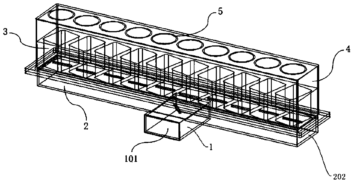
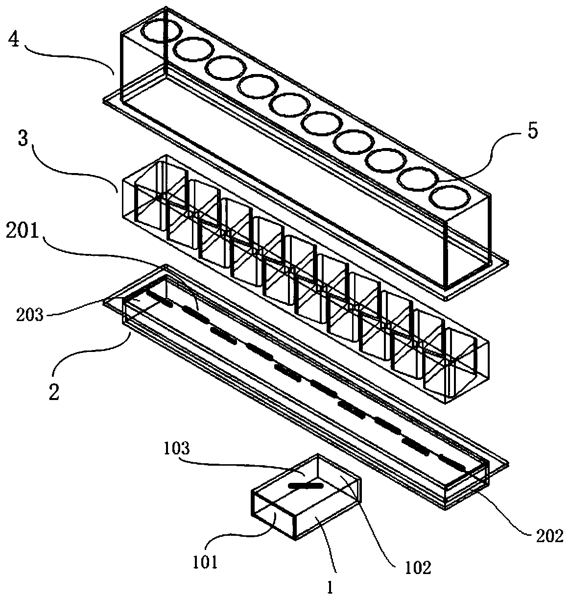
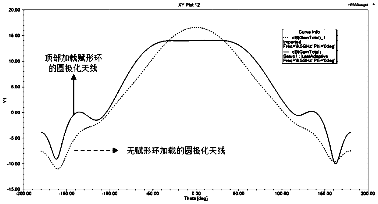
The shaped wide-beam circularly polarized antenna comprises a feed waveguide, a radiation waveguide, a circularly polarized open waveguide and a dielectric cover, the feed waveguide and the radiationwaveguide are connected or share the same wall, and a coupling piece is arranged between the feed waveguide and the radiation waveguide; the end face, away from the feed waveguide, of the radiation waveguide is provided with a plurality of slits used for generating linearly polarized waves, and the slits are evenly arranged in a staggered mode along the center line of the wide edge direction of the radiation waveguide. The circularly polarized open waveguide is connected with the radiation waveguide and is provided with open waveguide bodies in one-to-one correspondence with the slots; and thedielectric cover is sleeved on the circularly polarized open waveguide, the dielectric cover is provided with beam forming rings in one-to-one correspondence with the open waveguide bodies, and the waveform forming rings are used for broadening circularly polarized waves. Due to the fact that the circular polarization open waveguide is arranged in a rotating mode, conversion from electromagneticwave linear polarization waves to circular polarization is achieved, and information transmission and receiving are facilitated; due to the fact that the beam forming rings are arranged, the antenna can obtain fan-shaped beams with high gain.

Description

technical field [0001] The invention belongs to the technical field of wireless communication, in particular to a shaped wide-beam circularly polarized antenna. Background technique [0002] Circularly polarized antennas have broad application prospects in communications, radar, electronic countermeasures, telemetry and remote sensing, astronomy, and television broadcasting. Rolling aircraft communication; in electronic countermeasures, circularly polarized antennas can detect various linearly polarized or elliptically polarized electromagnetic waves of the enemy; in astronomy, spaceflight, remote sensing and telemetry, circularly polarized antennas can eliminate The polarization distortion effect of electromagnetic waves caused by the rotation effect; in broadcasting and television, circularly polarized antennas can overcome the ghosting phenomenon of video signals. [0003] In the existing technology, the pencil beam of the fire control radar only has the advantage of pre...

Claims


Application Information

Patent Timeline
Patent Type & Authority Applications(China)
IPC IPC(8): H01Q1/34H01Q1/36H01Q1/42H01Q1/50H01Q13/22H01Q15/24
CPCH01Q1/34H01Q1/36H01Q1/42H01Q1/50H01Q13/22H01Q15/244
Inventor 马岩冰叶声张宇环张瑞珏李亮苏醒渠芬芬苏晟
Owner SHANGHAI SPACEFLIGHT INST OF TT&C & TELECOMM
Learn More