

Vehicle light unit
a technology for vehicle lights and light tubes, applied in the field of vehicle lights, can solve the problems of obscuring the visibility of seals, difficult for light to reach the area where seals are attached, and plain seals
- Summary
- Abstract
- Description
- Claims
- Application Information
AI Technical Summary
Benefits of technology
Problems solved by technology
Method used
Image

Examples
Embodiment Construction
,” one will understand how the features of the present light unit provide several advantages over conventional vehicle light assemblies.
BRIEF DESCRIPTION OF THE DRAWINGS
[0012] These and other features, aspects and advantages of the present invention will now be described in connection with preferred embodiments of the invention, in reference to the accompanying drawings. The illustrated embodiments, however, are merely examples and are not intended to limit the invention. The following are brief descriptions of the drawings.
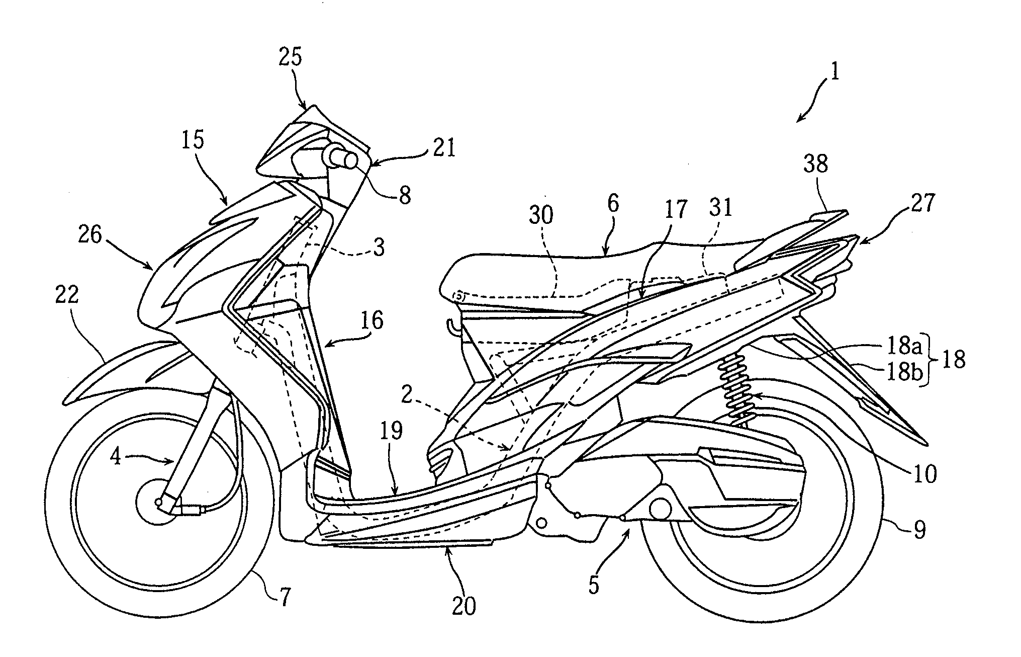
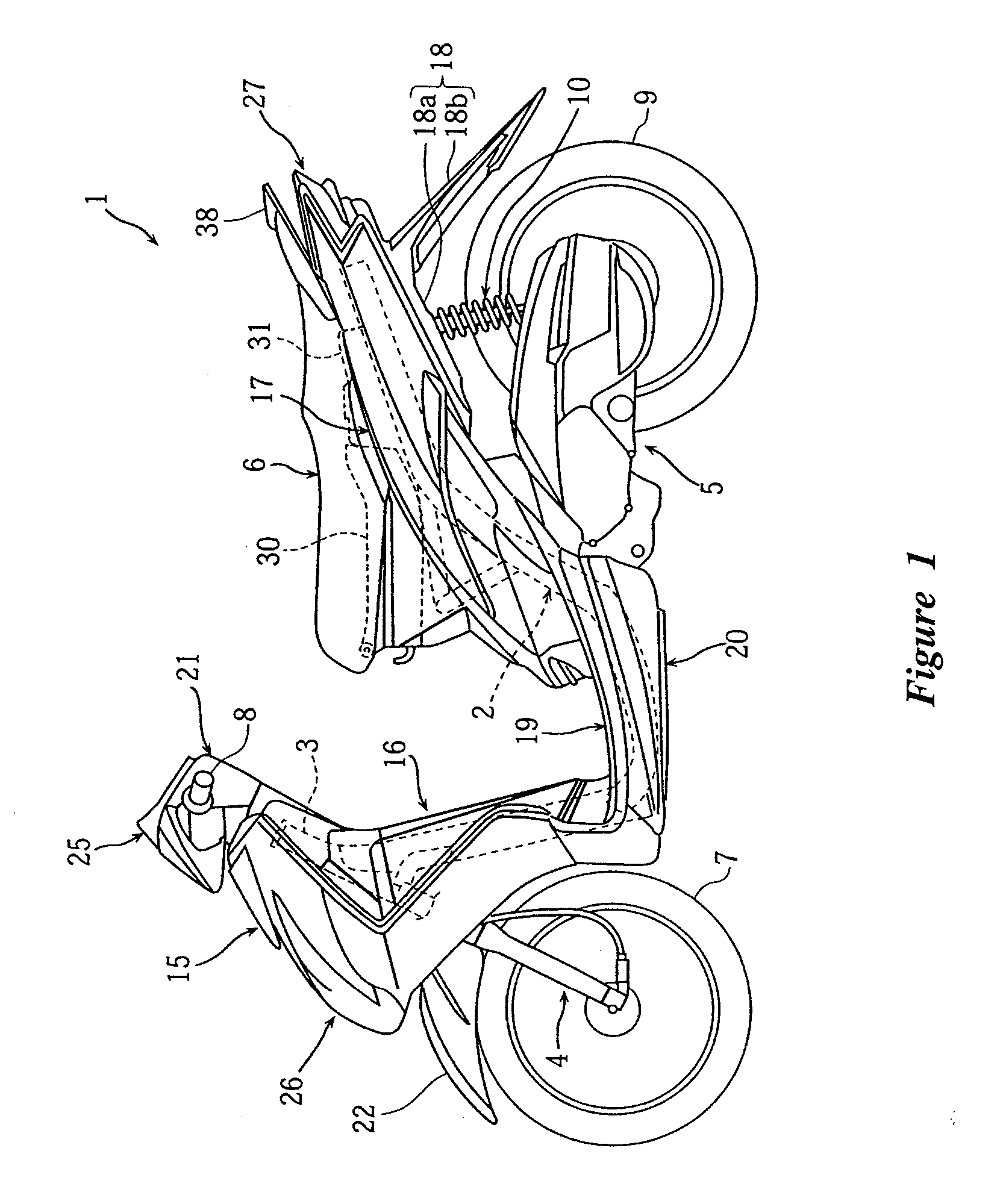
[0013]FIG. 1 is a side view of a motorcycle equipped with a tail lamp unit or light unit configured in accordance with a preferred embodiment of the present invention.
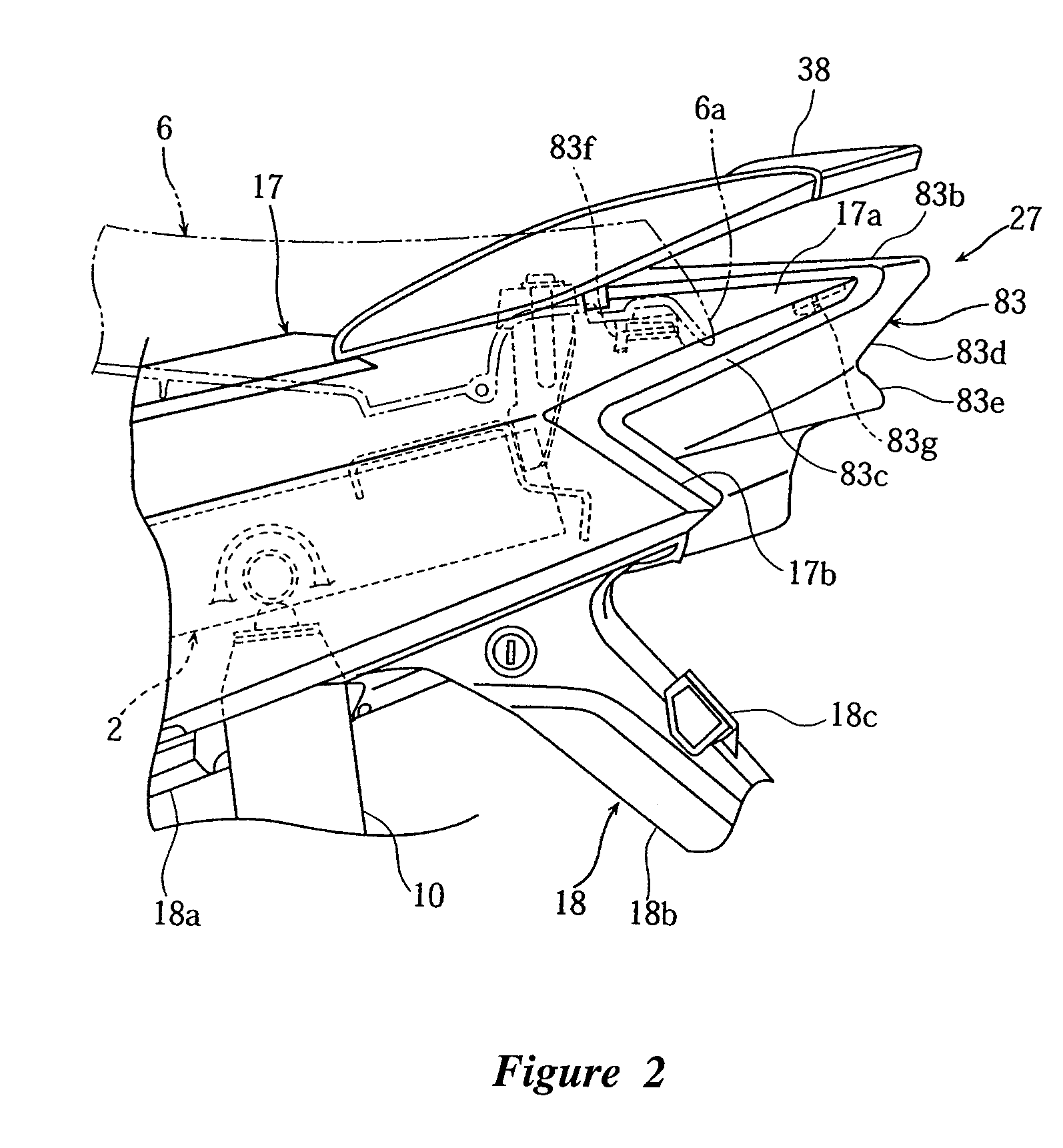
[0014]FIG. 2 is an enlarged partially side view of a rear portion of the motorcycle from FIG. 1 showing the light unit.
[0015]FIG. 3 is a plan view of the rear portion of the motorcycle from FIG. 2.
[0016]FIG. 4 is a plan view of the light unit from FIG. 3 removed from the motorcycle.
[0017]FIG. ...
PUM
 Abstract
Description
Claims
Application Information