

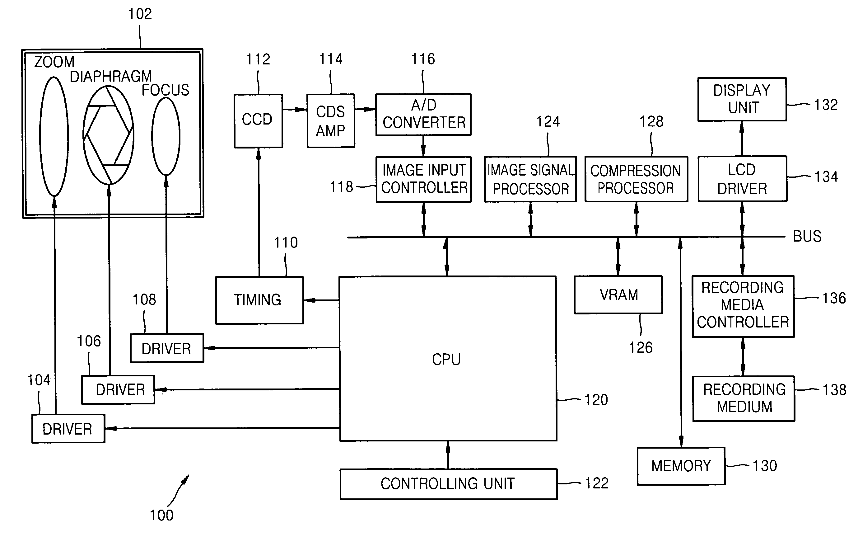
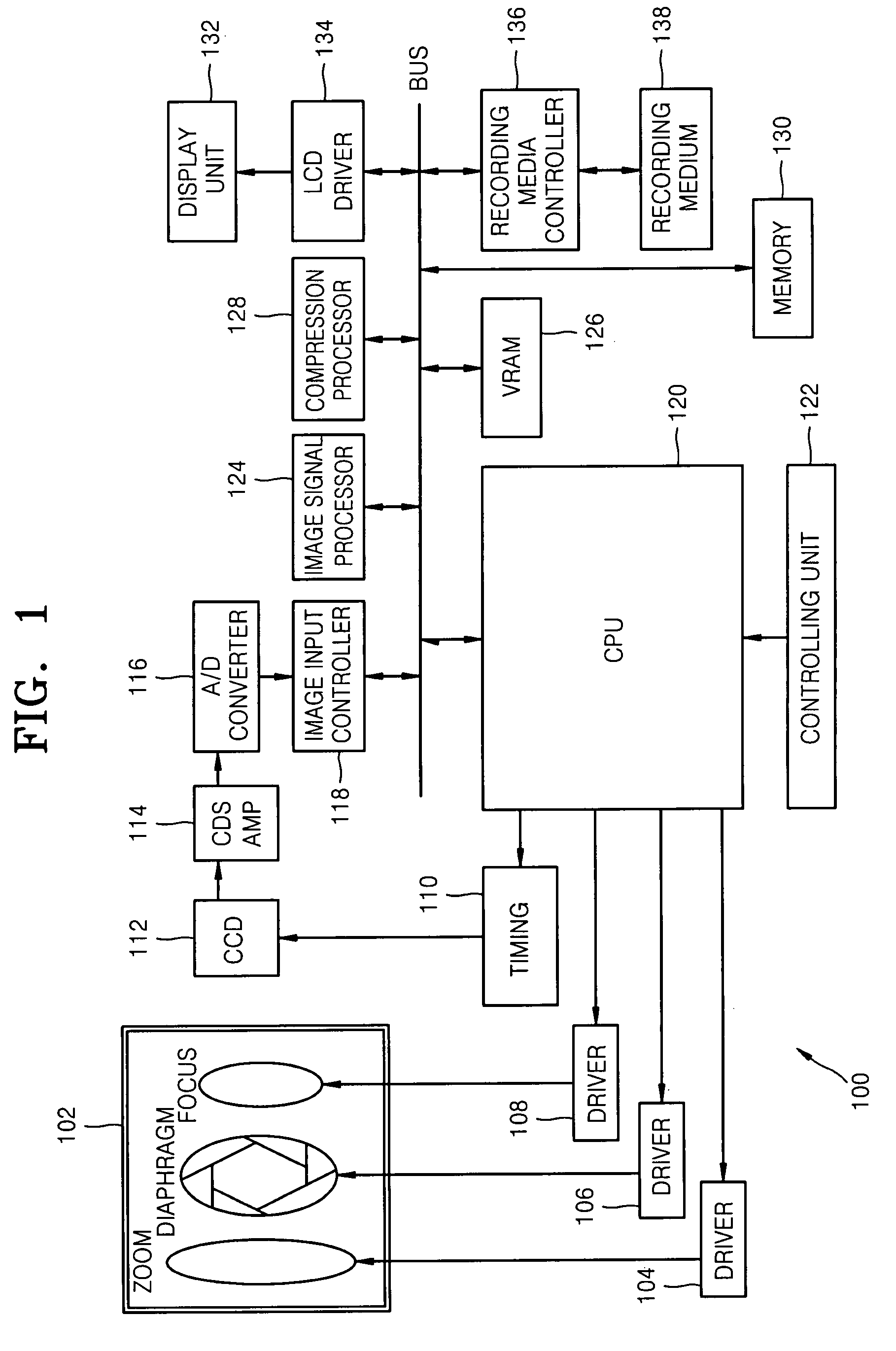
Apparatus and method for image pickup
a technology of image pickup and apparatus, applied in the field of apparatus and method for image pickup, can solve the problem of inaccurate removal of fixed pattern noise, and achieve the effect of reducing image noise, reducing shaking effect, and reducing image nois
- Summary
- Abstract
- Description
- Claims
- Application Information
AI Technical Summary
Benefits of technology
Problems solved by technology
Method used
Image

Examples
embodiment 1
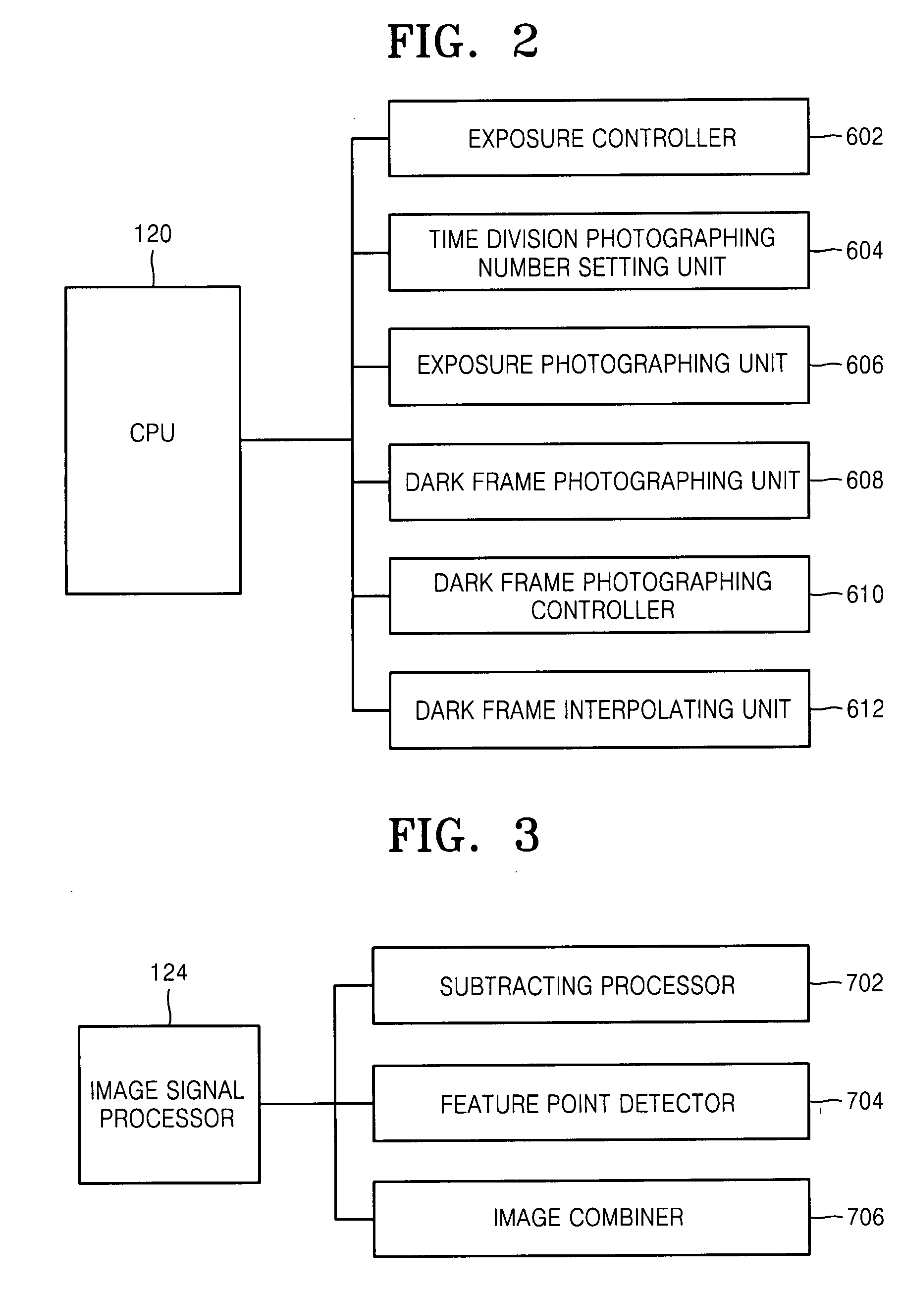
[0061]Referring to FIG. 8, the image pickup method according to an embodiment of the present invention will be described. FIG. 8 is a diagram illustrating an example of processes of individually subtracting the dark frame from each of the time-division images that are each photographed using the high shutter speed.
[0062]Reference numerals 402, 404, and 406 are time-division images photographed at a high shutter speed. Reference numeral 408 is a dark frame photographed in the dark state. The dark frame 408 is photographed at the same shutter speed as those of the images 402, 404, and 406 photographed in the exposure state. According to an embodiment of the present invention, the dark frame 408 is subtracted from each of the images 402, 404, and 406 to form subtracted images, and the subtracted images are combined to generate a combined image 410.
[0063]The noise reduction processes will be described with reference to FIG. 9 which is a flow chart illustrating an example of the photogra...
embodiment 2
[0065]Next, an image pickup method according to another embodiment of the present invention will be described with reference to FIG. 10. FIG. 10 is a flow chart illustrating an example image pickup processes according to the current embodiment. Descriptions for portions similar to the above embodiment will be omitted.
[0066]According to this second embodiment, the n number of high shutter speed images are photographed in the exposure state and the dark frame is photographed, and then, the subtractive images are formed. According to the current embodiment, whenever one high shutter speed image is photographed and stored in the memory in Step S204, a dark frame is photographed and stored in the memory in Step S206. Moreover, whenever the dark frame is stored, the dark frame is subtracted from the high shutter speed image to generate the subtractive image in Step S208. After generating the subtracted image, the high shutter speed image and the dark frame can be eliminated from the memor...
embodiment 3
[0068]An image pickup method according to another embodiment of the present invention will be described with reference to FIG. 11, which is a flow chart illustrating an example of image pickup processes according to the current embodiment. Descriptions for the portions similar to those of the above embodiments will be omitted.
[0069]As described above, according to the first embodiment, one dark frame is photographed, and thus, the noise reduction process can be performed at high speed and only a small memory capacity is required. In addition, according to the second embodiment, the time difference between the high shutter speed image and the dark frame is small, and the noise reduction can be performed accurately. Therefore, according to this third embodiment, a first dark frame is photographed after photographing a first high shutter speed image, a second dark frame is photographed after photographing a last (nth) high shutter speed image, and then, an interpolation calculation is ...
PUM
 Abstract
Description
Claims
Application Information