Image processing system and method for noise reduction

a processing system and noise reduction technology, applied in the field of image processing apparatuses, can solve the problems of difficult to ensure sufficient exposure at the time of image capture, blurred edges in images, and noisy captured images, etc., to achieve excellent image quality, reduce block distortion in images, and reduce noise in images

Active Publication Date: 2012-06-19
PANASONIC INTELLECTUAL PROPERTY CORP OF AMERICA
View PDF12 Cites 0 Cited by
  • Summary
  • Abstract
  • Description
  • Claims
  • Application Information

AI Technical Summary

Benefits of technology

[0039]According to the present invention, it is possible to reduce block distortion in images when reducing noise in the images using a temporal noise removal scheme, and thereby generating output images having an excellent image quality. Since no sudden change occurs in the temporally consecutive images, flickering and fluctuation phenomena can be reduced.

Problems solved by technology

With increase in camera speed and refinement of imaging elements, it has become difficult to ensure sufficient amounts of exposure at the time of image capturing.
For this reason, captured images include a lot of noise.
Noise removal using a spatial filter has problems that edges in an image are blurred in most cases and the saturation may decrease.
However, this scheme has a problem that, when there is a motion of a subject between the input image and the reference image, such pixel addition produces a residual image in the resulting output image.
However, there are cases where this scheme is not sufficient to perform accurate motion estimation due to influence of noise in images.
In such a case, an image region at the non-correspondence positions is added, which causes an adverse effect that especially still regions look fluctuating in resulting output images.

Method used


Image

  • Image processing system and method for noise reduction
  • Image processing system and method for noise reduction
  • Image processing system and method for noise reduction

Examples


Embodiment Construction

[0054]Hereinafter, an embodiment in the present invention is described with reference to the drawings.

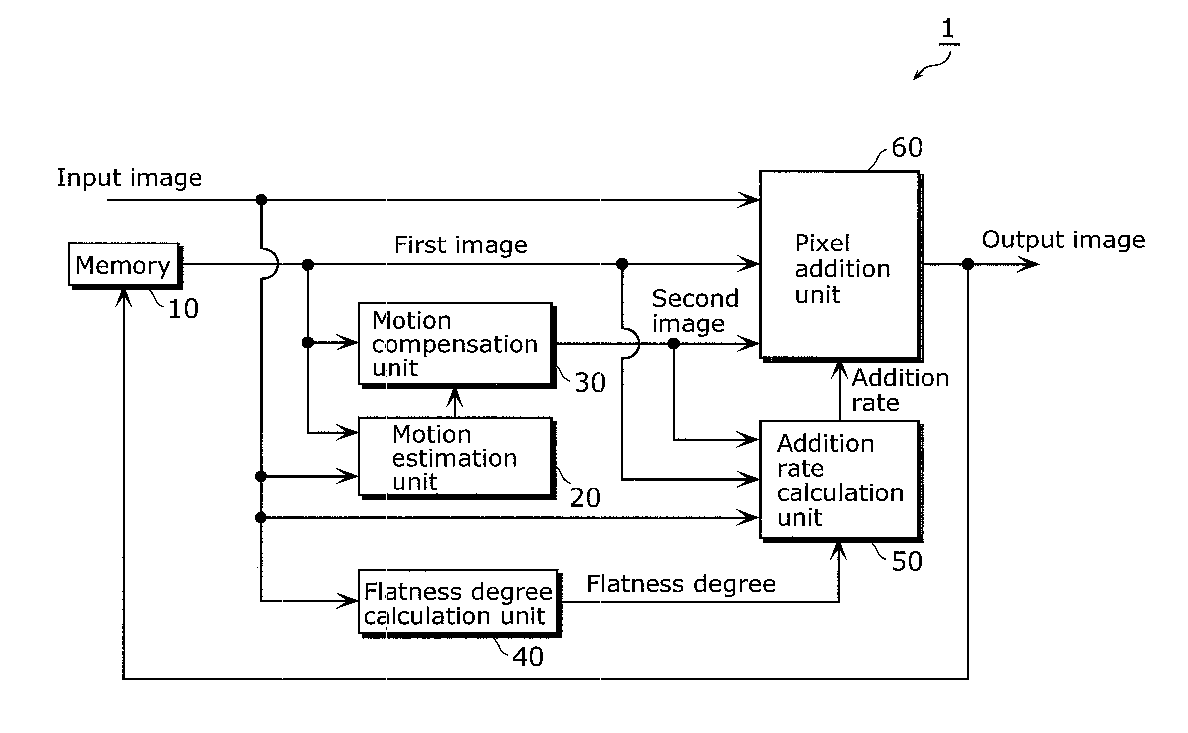
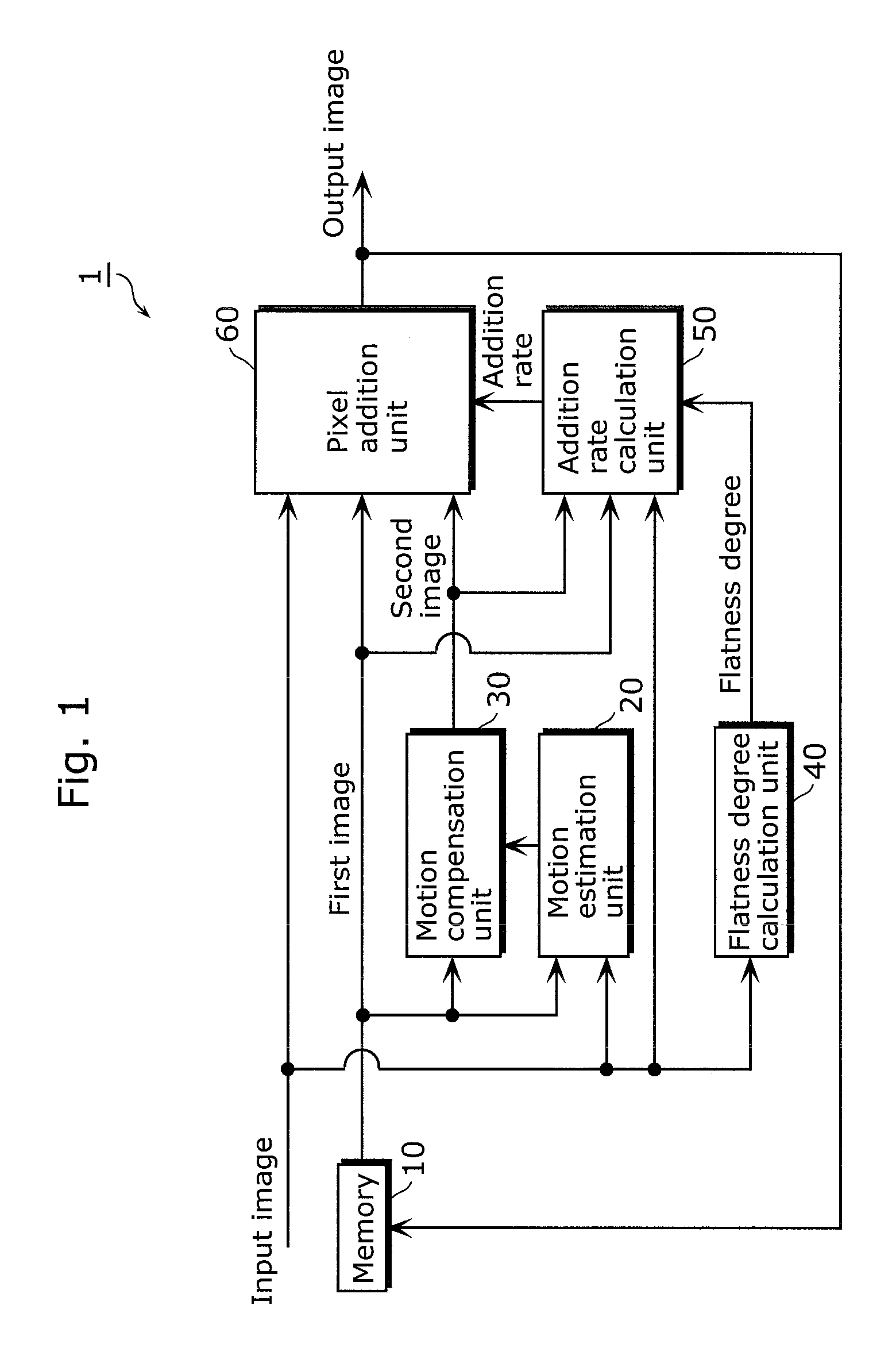
[0055]FIG. 1 is a functional block diagram showing a functional structure of an image processing apparatus 1 according to the embodiment of the present invention.

[0056]The image processing apparatus 1 is intended to remove noise in an input image by adding a reference image to the input image. As shown in the diagram, the image processing apparatus 1 includes a memory 10, a motion estimation unit 20, a motion compensation unit 30, a flatness degree calculation unit 40, an addition rate calculation unit 50, and a pixel addition unit 60.

[0057]The memory 10 is a memory storing a reference image for use in motion compensation. More specifically, the memory 10 stores an output image from the pixel addition unit 60 as a reference image.

[0058]The motion estimation unit 20 generates motion information indicating an estimated motion in the input image. More specifically, the motion estimatio...


PUM


Abstract

To provide an image processing apparatus which reduces, using a temporal noise removal scheme, image block distortion or noise and temporal flickering and fluctuation phenomena. The image processing apparatus (1) removing noise in an input image by adding a reference image to the input image includes a motion estimation unit (20) which generates motion information indicating a motion estimated for the input image; a motion compensation unit (30) which generates a after motion compensation second image corresponding to a before motion compensation first image by performing motion compensation using the generated motion information; a flatness degree calculation unit (40) which calculates a flatness degree of the input image; a blending rate calculation unit (53) which calculates addition rates for the input image, first image, and second image, using the calculated flatness degree; and a pixel addition unit (60) which adds the respective images according to the addition rates.

Description

TECHNICAL FIELD[0001]The present invention relates to image processing apparatuses capable of removing noise in input images and thereby suppressing flickering and fluctuation in resulting output images.BACKGROUND ART[0002]With increase in camera speed and refinement of imaging elements, it has become difficult to ensure sufficient amounts of exposure at the time of image capturing. For this reason, captured images include a lot of noise. Here, the noise in these images can be removed by signal processing. This noise removal can be roughly classified into spatial filtering and temporal noise removal.[0003]Noise removal using a spatial filter has problems that edges in an image are blurred in most cases and the saturation may decrease. On the other hand, temporal noise removal makes it possible to suppress the problems that occur in the noise removal using such a spatial filter and effectively removing noise.[0004]Some exemplary conventional temporal noise removal schemes are intende...

Claims


Application Information

Patent Timeline
Patent Type & Authority Patents(United States)
IPC IPC(8): G06K9/40G06K9/46G06K9/36H04N5/00G06T5/00H04N5/217
CPCG06T5/50G06T7/2013H04N19/577H04N5/21H04N19/61H04N19/86G06T2207/20021G06T2207/20221H04N5/144G06T7/223G06T5/00
Inventor NGUYEN, KHANGMONOBE, YUSUKETANJI, YUSUKE
Owner PANASONIC INTELLECTUAL PROPERTY CORP OF AMERICA
Why Eureka
Try Eureka