
Image processing device

a processing device and image technology, applied in the field of image processing devices, can solve the problem of not being able to sufficiently suppress afterimages of subjects in motion, and achieve the effect of suppressing afterimages and reducing image nois

Active Publication Date: 2017-12-12
HOYA CORP
View PDF27 Cites 0 Cited by
  • Summary
  • Abstract
  • Description
  • Claims
  • Application Information

AI Technical Summary

Benefits of technology

The invention aims to provide an image processing device that can suppress the afterimage of a moving subject while also reducing noise in an image.

Problems solved by technology

However, with the configuration recited in Patent Document 1, it is not possible to sufficiently separate the subject motion component from random noise, and therefore it is not possible to sufficiently suppress afterimages of a subject that is in motion.

Method used


Image

  • Image processing device
  • Image processing device
  • Image processing device

Examples


case 1

[0064

[0065]Case 1 is a case in which there are many regions with movement of the subject in the entire field, and there are few regions with movement of the subject in a local region. In Case 1, for example, portions with movement of the subject are widely distributed throughout the field, but the subject is not moving very much when a local region is viewed, and therefore although it is detected that the subject is moving in the entire field, it is detected that the subject is not moving in a local region.

case 2

[0066

[0067]Case 2 is a case in which there are few regions with movement of the subject in the entire field, and there are many regions with movement of the subject in a local region. In Case 2, for example, the subject is not moving very much when the entire field is viewed, but the subject is moving when a local region is viewed, and therefore although it is detected that the subject is moving in a local region, it is detected that the subject is not moving in the entire field.

[0068]In this way, in the case where the difference value calculated in processing step S18 is greater than or equal to the third threshold value, the result of subject motion detection differs between when the entire field is viewed and when a local region is viewed. For this reason, it is desirable that both the situation when viewing subject motion in the entire field and the situation when viewing subject motion in a local region are taken into consideration for the pixel signal of the pixel of interest ...

case 3

[0071

[0072]Case 3 is a case in which there are few regions with movement of the subject in the entire field, and there are also few regions with movement of the subject in a local region. In Case 3, for example, the subject is not moving very much when viewing not only the entire field, but also a local region, and therefore it is detected that the subject is not moving in any detection range.


PUM


Abstract

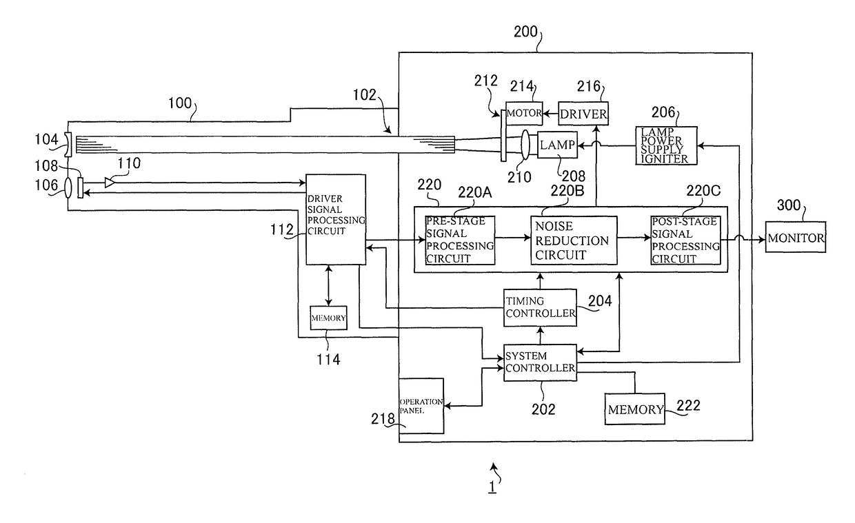
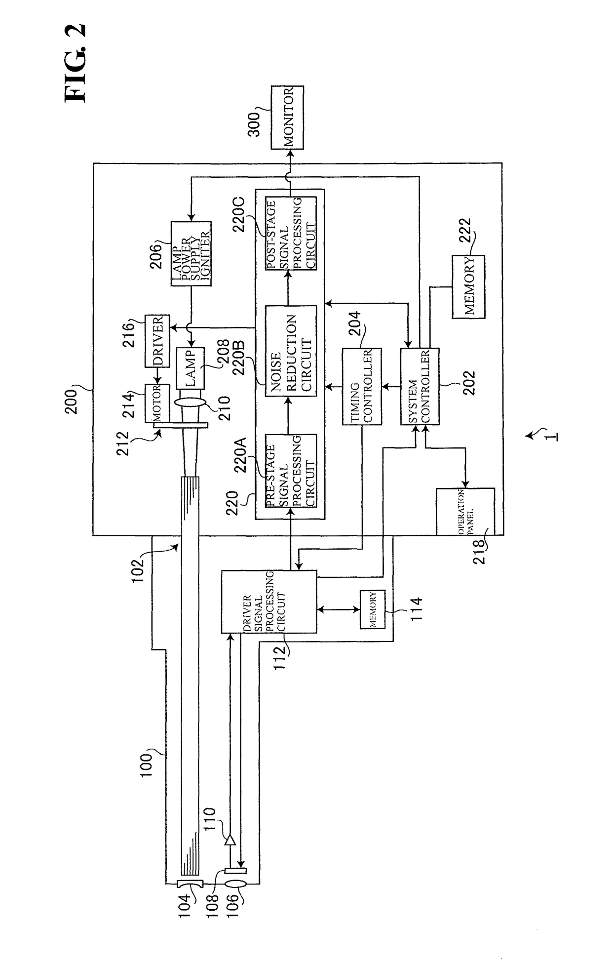
An image processing device is constituted by a device for detecting motion of the subject, with the entire effective pixel region as a range; a device for successively setting each of the pixels in the effective pixel region as a pixel of interest; a device for detecting motion of the subject, with a local pixel region that includes the successively set pixel of interest as a range; a device for, for each of the pixels of interest, determining a mixing ratio for the pixel signal of the current imaging period and the pixel signal of one imaging period earlier based on the two detection results; and a device for, for each of the pixels of interest, correcting the pixel signal of the current imaging period based on the determined mixing ratio.

Description

TECHNICAL FIELD[0001]The present invention relates to an image processing device that generates an image by processing a signal output from an imaging element.BACKGROUND ART[0002]Image processing devices that generate an image by processing a signal output by an imaging element are known. One known example of such an image processing device suppresses afterimages of a subject that is in motion while also reducing noise in images. A specific configuration of this type of image processing device is recited in JP 2000-209507A (hereinafter, called “Patent Document 1”), for example.[0003]The image processing device recited in Patent Document 1 includes a cyclic noise reduction circuit. The cyclic noise reduction circuit recited in Patent Document 1 uses a subtracter to obtain the difference between the current image signal output from an imaging element and the image signal of one frame earlier or one field earlier, uses a multiplier to multiply the difference value by a feedback coeffic...

Claims


Application Information

Patent Timeline
Patent Type & Authority Patents(United States)
IPC IPC(8): G06K9/40G06T5/00H04N9/07H04N5/232G06T7/223H04N5/21H04N5/14H04N23/12
CPCG06T5/002G06T7/223H04N5/21H04N9/07H04N5/23254H04N5/144G06T2207/20182H04N23/81H04N23/6811H04N23/12H04N23/60H04N23/683H04N25/60G06T5/70
Inventor YOKOUCHI, FUMIKA
Owner HOYA CORP
Learn More