Active matrix type display device and driving method thereof

A display device and active matrix technology, applied in lighting devices, static indicators, instruments, etc., can solve the problem of organic EL components 216 being extinguished, and achieve the effects of improving display quality, suppressing bad bright spots, and suppressing afterimages

Active Publication Date: 2010-10-13
SANYO ELECTRIC CO LTD
View PDF6 Cites 0 Cited by
  • Summary
  • Abstract
  • Description
  • Claims
  • Application Information

AI Technical Summary

Problems solved by technology

On the other hand, when the TFT 214 for driving becomes non-conductive in response to the display signal D supplied to the gate, since no current flows through the TFT 214 for driving, the organic EL element 216 is turned off.

Method used


Image

  • Active matrix type display device and driving method thereof
  • Active matrix type display device and driving method thereof
  • Active matrix type display device and driving method thereof

Examples


Embodiment Construction

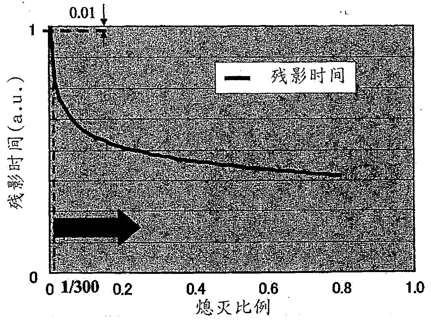
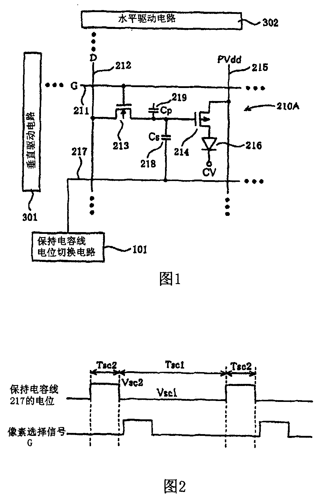
[0054] like figure 1 It is shown that the organic EL display device has: Connect the display pixel 210A to keep the capacitor line 217 hold the capacitor wire electrical switching circuit 101.The capacitance wire switching circuit 101 will keep the potential of the capacitor line 217 from the 1st potential VSC1 to the 2nd potential VSC2 higher than the 1st potential VSC1. The TFT214 used in the driver becomes a non -guidance state, and then keeps keeping it to keep it reserved again.The potential of the capacitor line 217 returns from the 2nd potential VSC2 to the 1st potential VSC1 to switch.

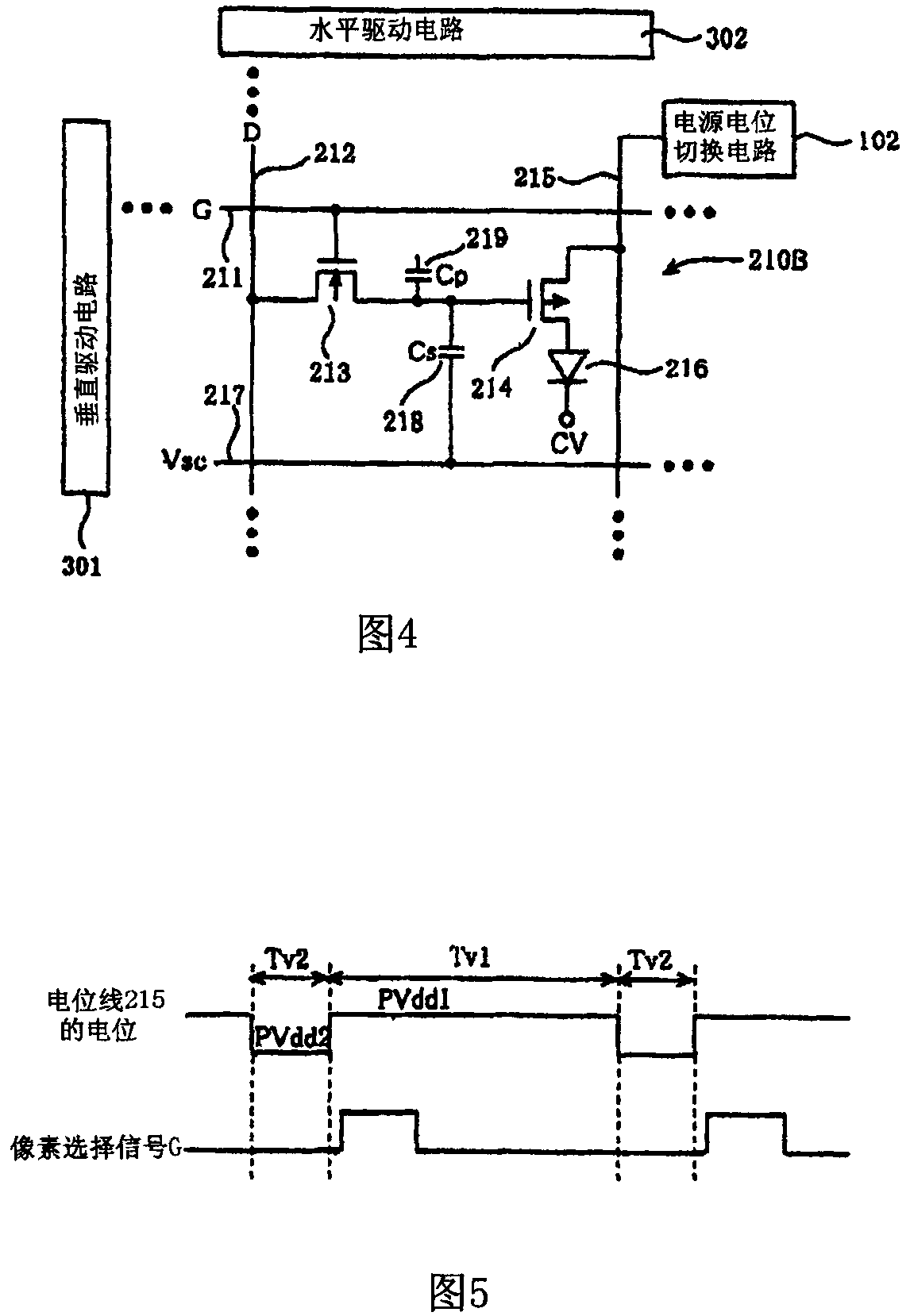
[0055] In addition, the organic EL display device involved in this implementation is preferably the specifications shown in the table.1 Table shows the values that can be obtained by PVDD, negative power potential CV, and the potentiometer vsig of the display signal D.In addition, in Table 1, channel width W, channel length L, carrier mobility μ, and grid polar capacitor COX represents the...


PUM


Abstract

A residual image effect is suppressed to improve quality of display of an active matrix type display device. A capacitor line electric potential switching circuit switches an electric potential of a capacitor line from a first capacitor electric potential Vsc 1 to a second capacitor electric potential Vsc 2 that is higher that the first capacitor electric potential Vsc 1 , while a power supply electric potential switching circuit switches an electric potential of a power supply line from a first power supply electric potential PVdd 1 to a second power supply electric potential PVdd 2 that is lower than the first power supply electric potential PVdd 1 . As a result of synergistic effect, an electric potential Vg at a gate of a driver TFT becomes higher than an electric potential at its source by more than a threshold voltage Vtp of the driver TFT. Assuming carriers are trapped in a gate insulation film of the driver TFT due to writing-in of a display signal in a preceding frame period,the carriers are extracted from the gate insulation film to the source or a drain of the driver TFT. With this, electric characteristics of the driver TFT are initialized.

Description

Technical field [0001] The invention is about the active matrix display device and its driver. Background technique [0002] In recent years, the development of organic electrical excitement components to replace CRT and LCD display devices (ORGANIC ELECTRO LUMINESCENCENCENCENCENCENCENCENCENCE: The following abbreviated referred to as [Organic EL component]).Especially the development of an active matrix organic EL display device with a Thin Filmtransistor (Switching Element) with a Switching Element (Switching Element). [0003] In the following, refer to the attachment to illustrate the active matrix organic EL display device. Figure 11 Indicates the equivalent circuit diagram of the organic EL display device.exist Figure 11 It only indicates that several display pixel 210 in a pixel 210 configured on the display panel is configured on the display panel. [0004] At the intersection of pixel selection signal line 211 and the display signal 212 extended in the line of the row di...

Claims


Application Information

Patent Timeline
Patent Type & Authority Patents(China)
IPC IPC(8): G09G3/30G09G3/20H05B33/08H05B33/14H05B44/00
CPCY02B20/343Y02B20/346
Inventor 小川隆司
Owner SANYO ELECTRIC CO LTD
Why Eureka
Try Eureka