Sensorless Flow Estimation for Implanted Ventricle Assist Device

a technology of assist device and sensorless flow, which is applied in the direction of prosthesis, catheter, therapy, etc., can solve the problems of insufficient patient care, inability to obtain accurate estimation of the flow rate of blood pumped by the vad, and collapse of the ventricle and damage to the myocardium

Active Publication Date: 2007-10-04
HEARTWARE INC
View PDF6 Cites 15 Cited by
  • Summary
  • Abstract
  • Description
  • Claims
  • Application Information

AI Technical Summary

Benefits of technology

[0009] Thrust bearings naturally encounter a drag as they rotate. Further by this invention, the viscosity of the blood may be predicted for a VAD, by de-powering the impeller and monitoring the rotational speed decay rate, which is generally proportional to viscosity of the blood. Thus, the viscosity of the blood can be quickly and easily estimated by measurement of the rotational speed decay rate of the impeller, typically for a time period which is no more than about 100 milliseconds, after which time the power is reapplied again. Thus, the patient does not suffer a severe, deleterious effect from the process.
[0012] These data provide the physician with information on the functioning of the blood pump, to assist in the control of the pumped flow rate, to maximize benefit to the patient.
[0014] An additional difficulty in estimating flow rate within a patient is that the body system resistance varies with time. A body's physiologic needs varies with activity and level of stress or anxiety. A rotary ventricular assist device may have to change rotational speed to best meet the transient, physiological needs. The steady state, conventional head-flow curves do not take into account the impeller inertia, or the lag time to change rotary speeds. An empirical relationship can be developed between the rate of change of rotational speed and the difference of actual flow rate and steady-state flow rate. This correction term can allow the estimation of instantaneous flow rates, which may vary over a very short period of time ranging down to about 10 milliseconds. An analogous relationship can be developed for pump head pressures.
[0017] The result of this is to provide a surprising accuracy to the estimated VAD blood flow rate (and pump head) to recognize the transient changes of impeller rotation over time. These transient changes can be charted with the time periods mentioned above being down to about the 10 millisecond level, to create a chart of pump head variation over time and pump flow over time. From these curves the actual beating of the natural heart can be recognized, and, in the manner of a cardiogram, it is believed that functioning of the valves and most or all of the data that can be achieved from a cardiogram can be observed in accordance with this invention, merely from the raw data of the pump impeller rotation rate and the power (or absence thereof) applied to the pump. These data may be electronically monitored by the VAD, so that the pumping rate of the VAD may be optimally controlled, and data from the native heart may be determined throughout the days and nights without the need of setting up a cardiogram for the patient. Thus, the condition of the native heart may be more easily monitored over the passage of time by the cardiologist. Particularly, the native heart flow rate and other real time diagnostic information may be provided for the attending physician, while the flow and pump head estimates can be used to determine cardiovascular resistance characteristics.

Problems solved by technology

However, too much flow through the ventricle assist device (VAD) can lead to ventricle collapse and damage to the myocardium.
Too little flow can result in the VAD not producing proper therapeutic support for the patient.
However, a problem arises in the obtaining of a reliable flow estimate for a particular clinical situation, using the standard performance curves for a particular pump.
Thus, without careful and continuous monitoring of the viscosity of the blood of the patient, one cannot obtain an accurate estimate of the flow rate of the blood pumped by the VAD.
This, of course, renders difficult or impossible an estimate on how the native heart is performing, and other clinical data becomes effectively unavailable from the data that can be obtained from the ventricle assist pump device itself.
Without such sensors, much accurate clinical data pertaining to the patient has been unavailable from an analysis of data from the VAD pump.

Method used


Image

  • Sensorless Flow Estimation for Implanted Ventricle Assist Device
  • Sensorless Flow Estimation for Implanted Ventricle Assist Device
  • Sensorless Flow Estimation for Implanted Ventricle Assist Device

Examples


example

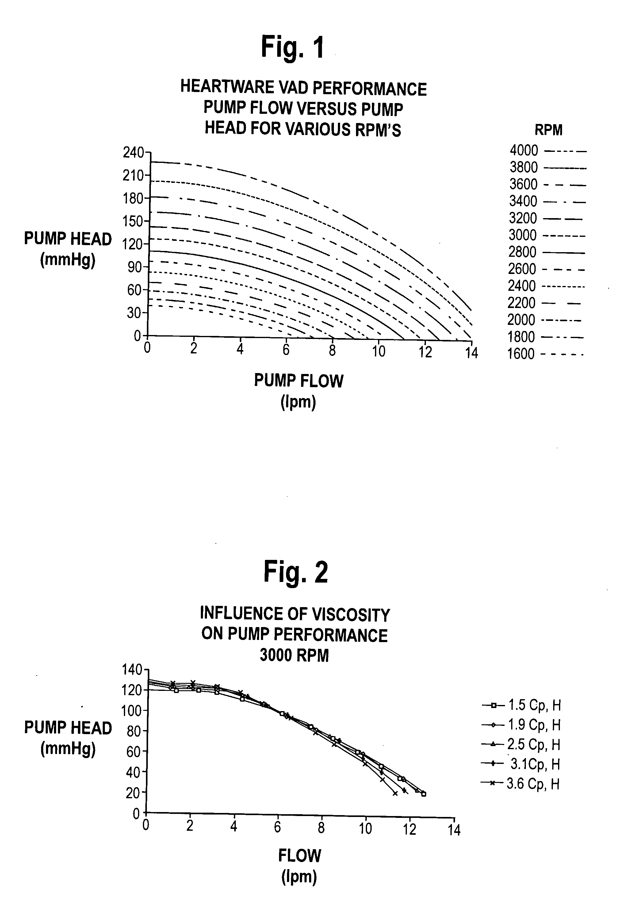
[0052] An in vitro test of blood pumping was performed, using a Heartware VAD.

[0053] Step 1. Obtain Fluid Viscosity

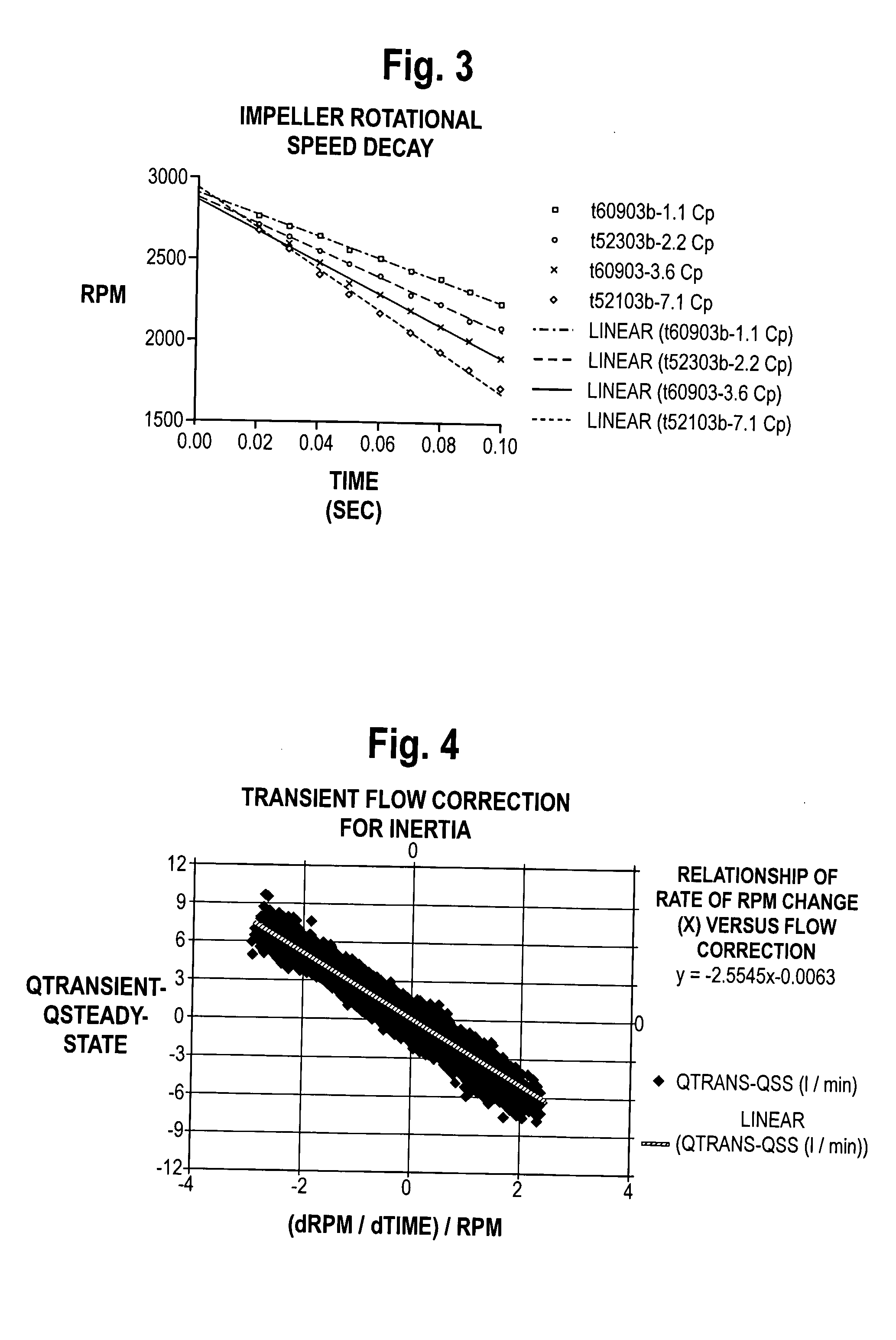
[0054] The rotational speed decay was monitored by depowering the impeller of the VAD while it was initially operating at 3,000 rpm. The rotational speed decay was measured in accordance with the Table I below:

[0055] We collected rotational speed (i.e., RPM) for several time increments to obtain the rotational speed decay rate after depowering:

TABLE ITime (sec)RPM0.0030000.0228400.0426800.062515

[0056] Using a linear curve fitting routine, the initial rotational speed decay rate (i.e., dRPM / dTime is determined to be −8080 RPM / sec from the Table 1 data. An empirical relationship that characterizes the rate of rotational speed decay rate vs. fluid viscosity can be developed prior to installation of a VAD in a patient. Such a relationship is illustrated in FIG. 6, and is determined for the particular pump by experimentation.

[0057] The calculated speed decay rate (−808...


PUM


Abstract

A method of estimating the blood flow rate of a heart ventricle assist device which is positioned externally of, or implanted in, a patient. The assist device comprises a blood pump having a rapidly rotating, electrically powered impeller, and comprises briefly interrupting power to the impeller to cause its rotation to slow. From this, blood viscosity can be estimated, which viscosity is used to obtain real time, estimated blood flow rates and pressure heads. Apparatus for accomplishing this is disclosed.

Description

BACKGROUND OF THE INVENTION [0001] The measurement of blood flow is an essential component for physiological control of a ventricle assist device, to assist the heart in functioning. Such devices are well known, and, as indicated for example in U.S. Pat. Nos. 6,149,683; 6,158,984; 6,234,772; and 6,368,083 may comprise a blood pump having a rapidly rotating, electrically powered impeller for pumping of blood, generally in a supplemental manner, to assist a failing heart. However, too much flow through the ventricle assist device (VAD) can lead to ventricle collapse and damage to the myocardium. Too little flow can result in the VAD not producing proper therapeutic support for the patient. Thus, the blood flow provided by the VAD must be closely monitored at all times. [0002] For a VAD utilizing a rotary pump, the only parameters which are available for flow estimation, in the absence of supplemental sensors, are the rotational speed of the impeller and the power or the electrical cur...

Claims


Application Information

Patent Timeline
Patent Type & Authority Applications(United States)
IPC IPC(8): A61B5/02A61M1/10A61M1/12A61N1/362
CPCA61M1/101A61M1/122A61M2205/3379A61M2205/3334A61M60/148A61M60/411A61M60/216A61M60/523A61M60/178A61M60/117A61M60/825
Inventor LAROSE, JEFFREY A.SINGH, UDAI
Owner HEARTWARE INC
Why Eureka
Try Eureka