Sensorless flow estimation for implanted ventricle assist device

Active Publication Date: 2005-12-01
HEARTWARE INC
View PDF13 Cites 23 Cited by
  • Summary
  • Abstract
  • Description
  • Claims
  • Application Information

AI Technical Summary

Problems solved by technology

However, too much flow through the ventricle assist device (VAD) can lead to ventricle collapse and damage to the myocardium.
To little flow can result in the VAD not producing proper therapeutic support for the patient.
However, a problem arises in the obtaining of a reliable flow estimate for a particular clinical situation, using the standard performance curves for a particular pump.
Thus, without careful and continuous monitoring of the viscosity of the blood of the

Method used


Image

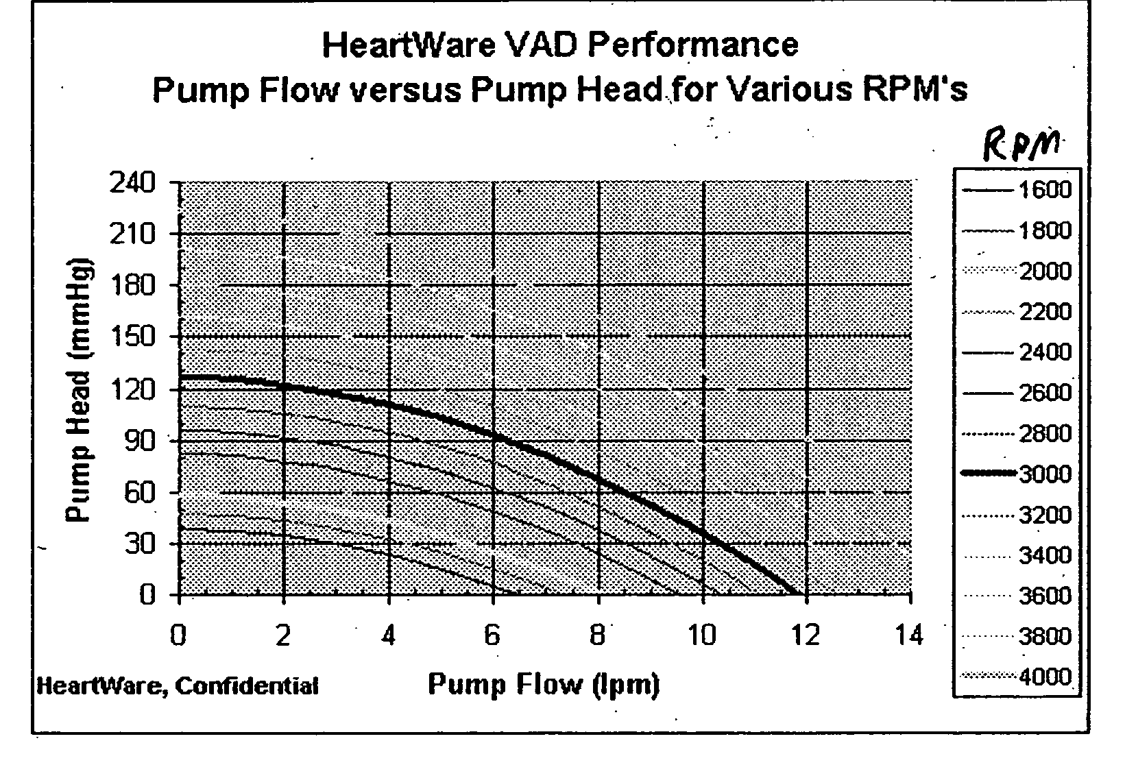
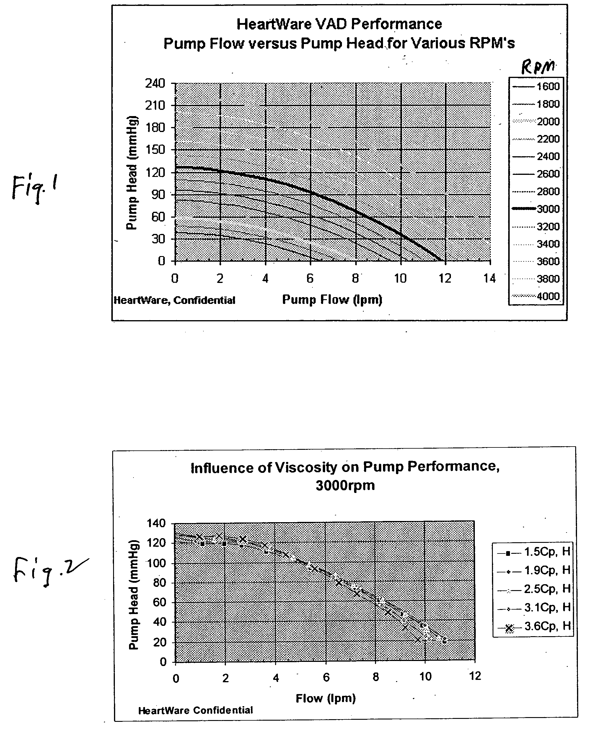
  • Sensorless flow estimation for implanted ventricle assist device
  • Sensorless flow estimation for implanted ventricle assist device
  • Sensorless flow estimation for implanted ventricle assist device

Examples


example

[0038] An in vitro test of blood pumping was performed, using a Heartware VAD.

[0039] Step 1. Obtain Fluid Viscosity

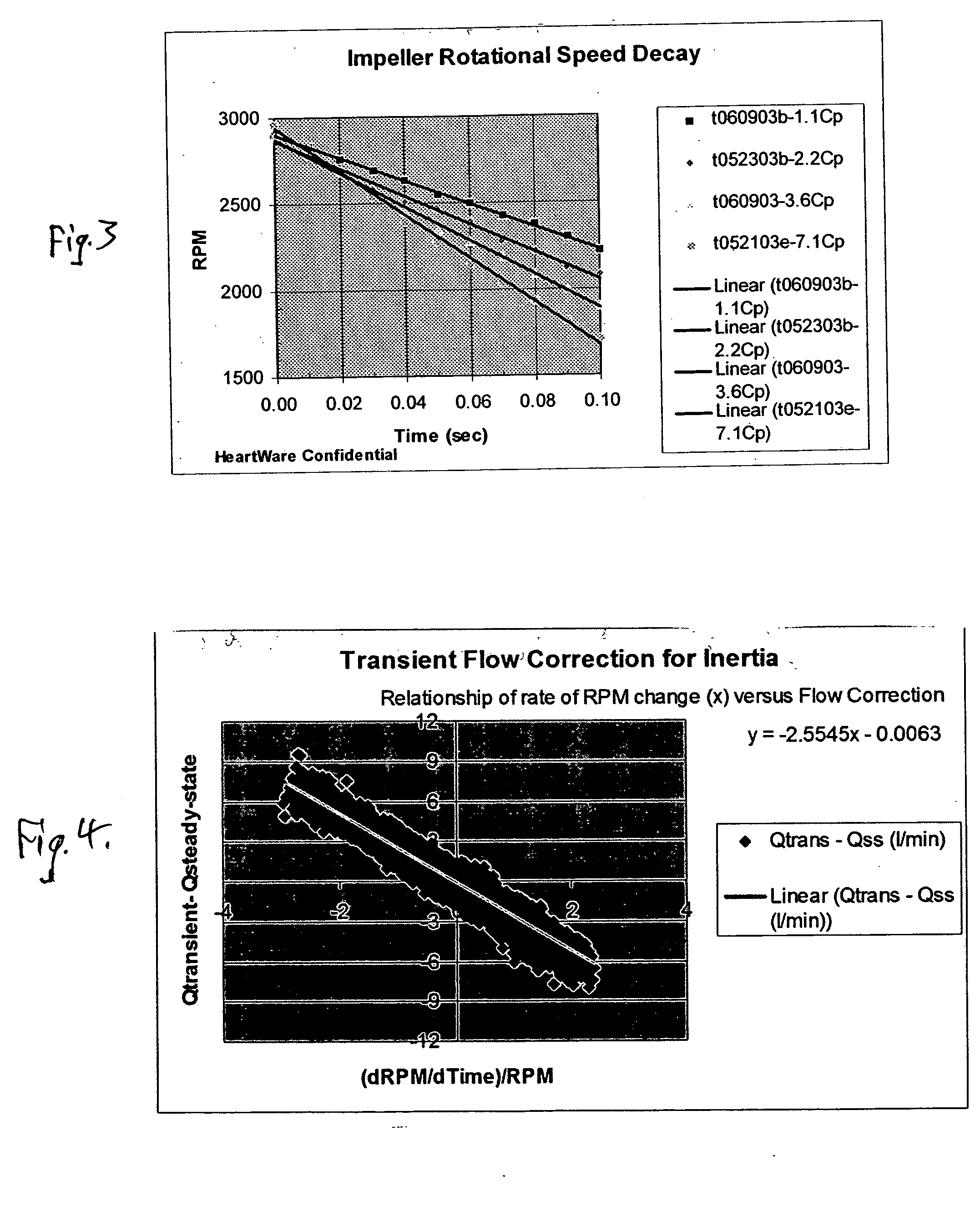
[0040] The rotational speed decay was monitored by depowering the impeller of the VAD while it was initially operating at 3,000 rpm. The rotational speed decay was measured in accordance with the Table I below:

[0041] We collected rotational speed (i.e., RPM) for several time increments to obtain the rotational speed decay rate after depowering:

TABLE 1Time (sec)RPM0.0030000.0228400.0426800.062515

[0042] Using a linear curve fitting routine, the initial rotational speed decay rate (i.e., dRPM / dTime is determined to be −8080 RPM / sec from the Table 1 data. An empirical relationship that characterizes the rate of rotational speed decay rate vs. fluid viscosity can be developed prior to installation of a VAD in a patient. Such a relationship is illustrated in FIG. 6, and is determined for the particular pump by experimentation.

[0043] The calculated speed decay rate (−808...


PUM


Abstract

A method of estimating the blood flow rate of a heart ventricle assist device which is positioned externally of, or implanted in, a patient. The assist device comprises a blood pump having a rapidly rotating, electrically powered impeller, and comprises briefly interrupting power to the impeller to cause its rotation to slow. From this, blood viscosity can be estimated, which viscosity is used to obtain real time, estimated blood flow rates and pressure heads.

Description

BACKGROUND OF THE INVENTION [0001] The measurement of blood flow is an essential component for physiological control of a ventricle assist device, to assist the heart in functioning. Such devices are well known, and, as indicated for example in U.S. Pat. Nos. 6,149,683; 6,158,984; 6,234,772; and 6,368,083 may comprise a blood pump having a rapidly rotating, electrically powered impeller for pumping of blood, generally in a supplemental manner, to assist a failing heart. However, too much flow through the ventricle assist device (VAD) can lead to ventricle collapse and damage to the myocardium. To little flow can result in the VAD not producing proper therapeutic support for the patient. Thus, the blood flow provided by the VAD must be closely monitored at all times. [0002] For a VAD utilizing a rotary pump, the only parameters which are available for flow estimation, in the absence of supplemental sensors, are the rotational speed of the impeller and the power or the electrical curr...

Claims


Application Information

Patent Timeline
IPC IPC(8): A61M1/10A61M1/12A61N1/362
CPCA61M1/101A61M1/122A61M2205/3379A61M2205/3334A61M60/148A61M60/411A61M60/216A61M60/523A61M60/178A61M60/117A61M60/825
Inventor LAROSE, JEFFREY A.
Owner HEARTWARE INC
Why Eureka
Try Eureka