Method for controlling agricultural machine systems

a technology of agricultural machines and systems, applied in the direction of process and machine control, vehicle position/course/altitude control, instruments, etc., can solve the problems of a large amount of time, the window of time is often not used in an optimal manner, and the amount of time available for work to be carried out is usually limited, so as to achieve cost-favorable effects

Active Publication Date: 2007-10-04
CLAAS SELBSTFAHRENDE ERNTEMASCHINEN GMBH
View PDF5 Cites 141 Cited by
  • Summary
  • Abstract
  • Description
  • Claims
  • Application Information

AI Technical Summary

Benefits of technology

[0008]An object of the present invention, therefore, is to create a time-saving and, therefore, more cost-favorable method for controlling several agricultural machine systems that also have different machine parameters in particular, and to create a control system therefor.

Problems solved by technology

For specific applications, harvesting in particular, the amount of time available within which work can be carried out is usually limited, usually due to the weather, and this window of time is often not used in an optimal manner due to lack of resource planning.
This type of procedure takes a relatively great deal of time.

Method used


Image

  • Method for controlling agricultural machine systems
  • Method for controlling agricultural machine systems
  • Method for controlling agricultural machine systems

Examples


Embodiment Construction

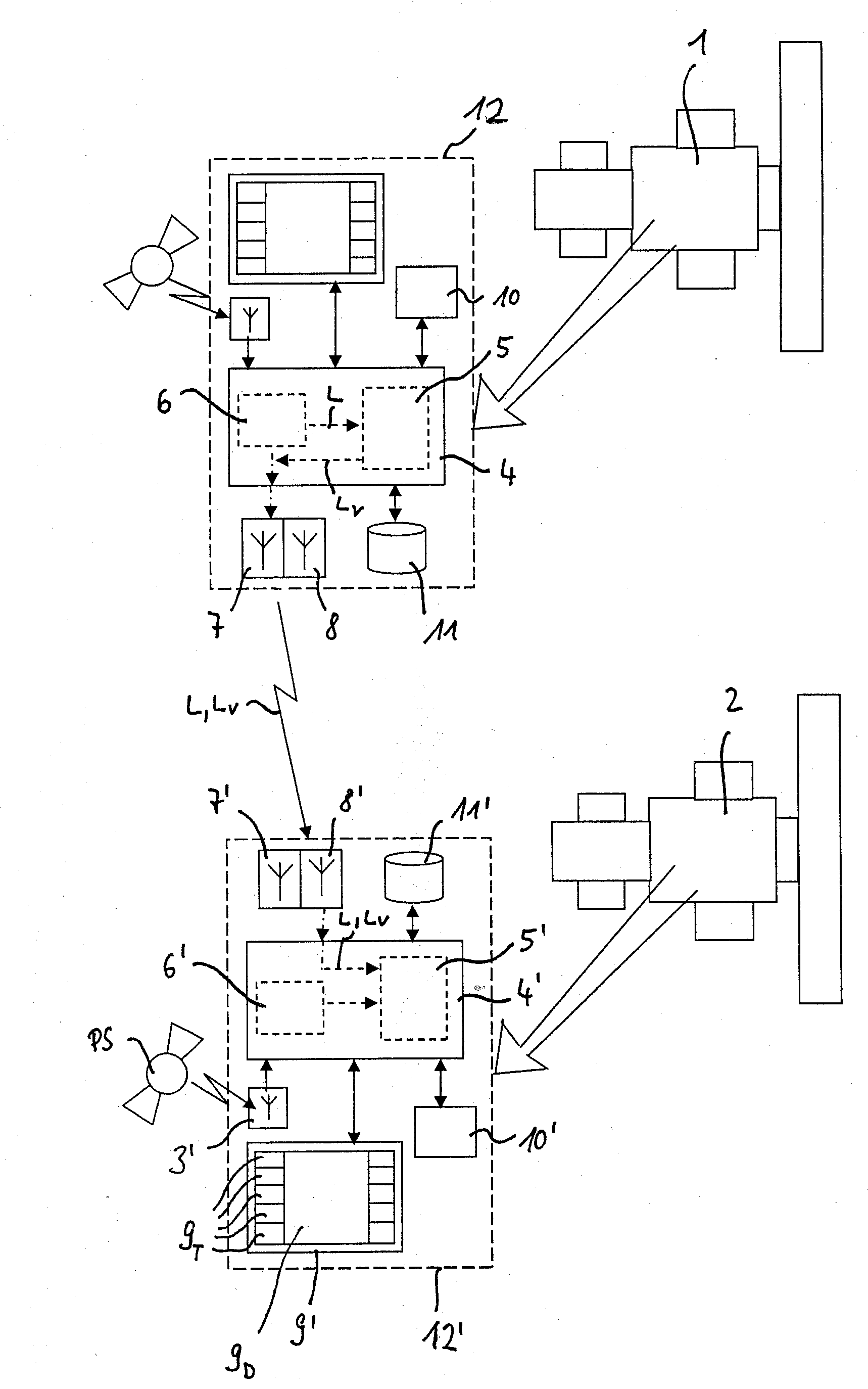
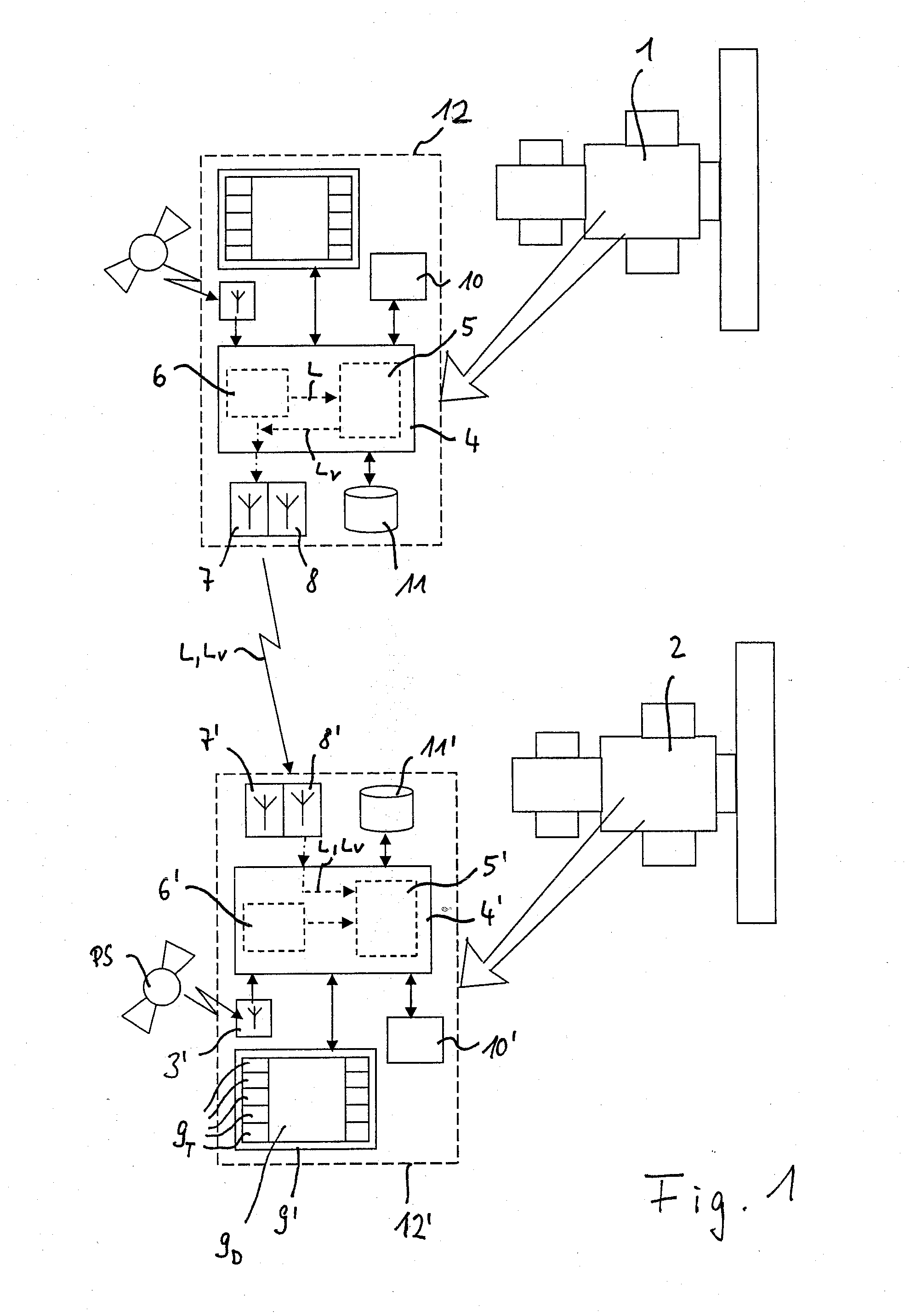
[0036]With the exemplary embodiment of the inventive control system shown in FIG. 1, only two identically configured machine systems 1, 2—two combine harvesters in this case—are shown, for simplicity. They can be used together in a group of machines, e.g., to work a large area in the shortest possible time.

[0037]The design and mode of operation of combine harvesters 1, 2 are basically known to one skilled in the art, as are suitable control systems for controlling combine harvesters 1, 2. In addition, suitable route planning systems are made known in EP 0 821 296 A1 and DE 10 2004 027 242 A2. Reference is hereby made to the entire contents of these publications. Therefore, only those components of control systems 12, 12′ in combine harvesters 1, 2 that are required to explain the present invention are depicted schematically in FIG. 1. Control systems 12, 12′—which, taken together, form an inventive control system—basically have the same design in both combine harvesters 1, 2.

[0038]I...


PUM


Abstract

For controlling several agricultural machine systems during operation on a territory, based on a reference line, an optimized route for working the territory is determined for the particular machine system, and the particular machine system is driven along this route. The reference line is determined by recording a reference path that was driven along with a first machine system, and the first machine system is controlled based on this reference line with consideration for the working conditions of the first machine system. This reference line is also transmitted by the first machine system to at least one second machine system, which is controlled based on this reference line of the first machine system and with consideration for the working conditions of the second machine system. A corresponding control system for controlling several agricultural machine systems during operation of a territory is also described.

Description

CROSS-REFERENCE TO A RELATED APPLICATION[0001]The invention described and claimed hereinbelow is also described in German Patent Application DE 10 2006 015 203.4 filed on Mar. 30, 2006. This German Patent Application, whose subject matter is incorporated here by reference, provides the basis for a claim of priority of invention under 35 U.S.C. 119(a)-(d).BACKGROUND OF THE INVENTION[0002]The present invention relates to a method for controlling several agricultural machine systems during operation on a territory, with which, based on a reference line, an optimized route for working the territory is determined for the particular machine system, then the particular machine system is driven along this route.[0003]The present invention also relates to a corresponding control system for controlling several agricultural machine systems.[0004]Given that the performance of agricultural machine systems, i.e., working vehicles such as combine harvesters or forage harvesters, and tractors with ...

Claims


Application Information

Patent Timeline
Patent Type & Authority Applications(United States)
IPC IPC(8): G06F19/00
CPCA01D41/1278A01B69/008G05D1/0219G05D1/0291G05D2201/0201
Inventor DIEKHANS, NORBERTHUSTER, JOCHENBRUNNERT, ANDREASHELLIGEN, LARS-PETER MEYER ZU
Owner CLAAS SELBSTFAHRENDE ERNTEMASCHINEN GMBH
Why Eureka
Try Eureka