Electrically conductive pipe or cable clip

Inactive Publication Date: 2005-06-28
DAUME PATENTBESITZGMBH
View PDF17 Cites 23 Cited by
  • Summary
  • Abstract
  • Description
  • Claims
  • Application Information

AI Technical Summary

Benefits of technology

[0006]The core concept of the inventive teachings resides in the fact that, in lieu of a metallic mesh hoop, a contact element of profiled sheet metal is used.

Problems solved by technology

Furthermore, the contact element formed of pro

Method used


Image

  • Electrically conductive pipe or cable clip
  • Electrically conductive pipe or cable clip
  • Electrically conductive pipe or cable clip

Examples


first embodiment

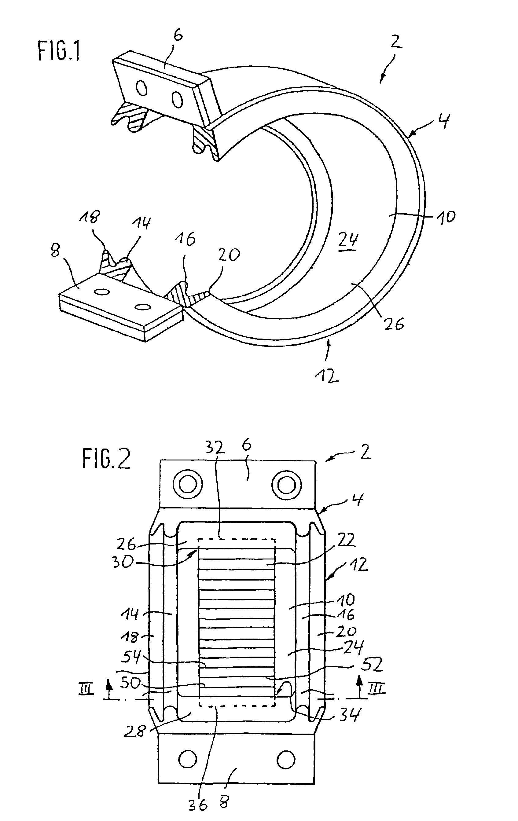
[0066]As seen in FIG. 1, the device 2 of the present invention is illustrated which comprises a base structure 4 formed as a bendable collar, which, in this embodiment, is formed as a single piece and is configured to be open in the circumferential direction and comprises, on its free ends, outwardly angled interconnecting plates, 6, 8, which are connectable to one another in the contact mounting position in a manner described in more detail with respect to FIG. 4.

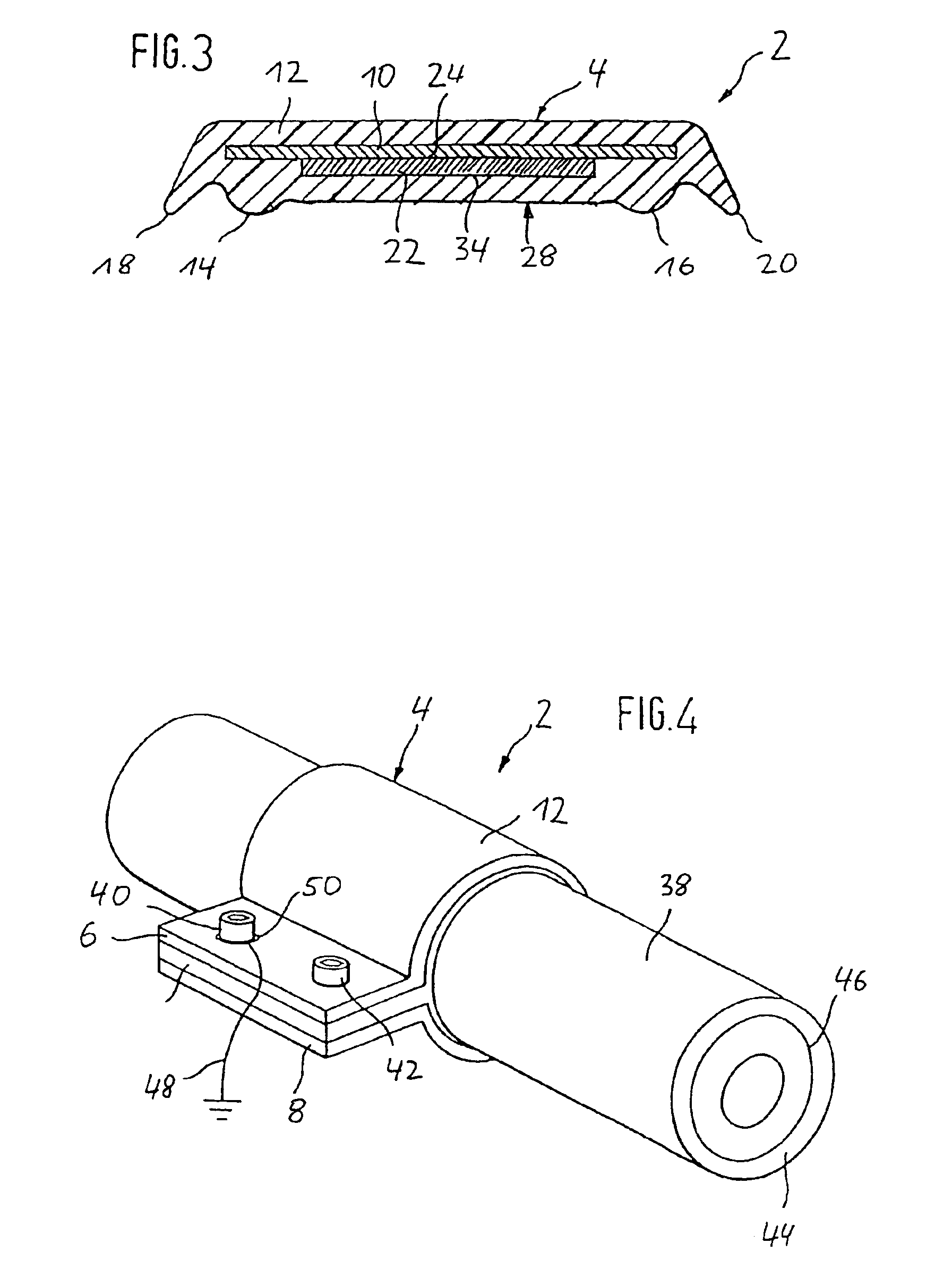
[0067]The base structure 4 includes a support element 10 formed of metal as well as a component 12 formed of elastic material, which in the embodiment, is comprised of an elastomer such as, for example, vulcanized rubber or a thermoplastic elastomer. The support element 10 is embedded, via its axial edges, in the component 12 formed of elastic material and is thereby firmly connected therewith (compare FIG. 3).

[0068]The component 12 formed of elastic material forms, on the side of the base structure 4 turned toward the bod...

second embodiment

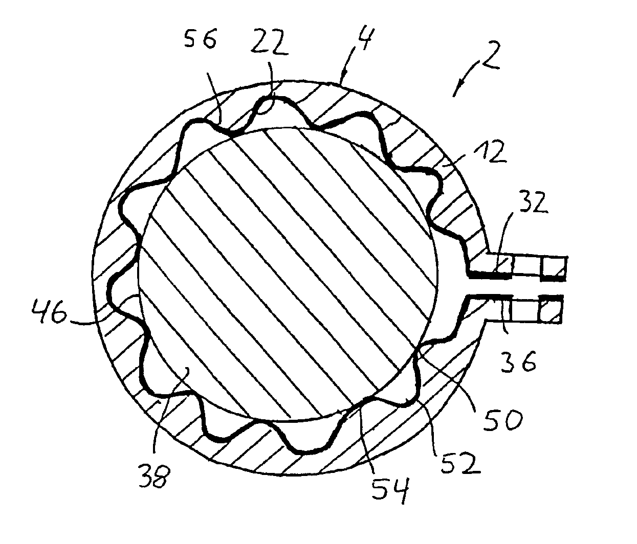
[0086]FIG. 9 shows the inventive device 2 whose principal difference relative to the embodiment shown in FIG. 1 is that the base structure 4 is formed completely of an elastic material. The base structure 4 comprises a disposition surface 56 on the side of the base structure facing toward the contact element 22 which is substantially complementarily configured with respect to the profile of the contact element 22 such that, as can be seen in FIG. 9, the contact element 22 is, in the circumferential direction, disposed over substantially its entire length on the disposition surface 56. The contact element 22 is coated with the elastic material of the base structure 4 in the circumferential direction and is thus firmly connected with the elastic material.

[0087]As can be further seen in FIG. 9, the contact element 22 extends fully to each of the interconnecting plates 6, 8. In this connection, through bores are formed in the end 32 of the contact element 22 and threaded bores are forme...


PUM


Abstract

A device for forming an electrically conductive contact with an electrically conductive component of an elongated body is provided. The device includes a base structure for disposition on the body to be contacted, and a separate contact element for contacting the body in a contact mounting position for producing an electrically conductive connection between the electrically conductive component and a ground cable. The contact element is formed of profiled sheet metal. The base structure is comprised of an elastic material that on the side turned toward the contact element comprises a disposition surface for the disposition of the contact element thereon over substantially the entire length of the contact element.

Description

BACKGROUND OF THE INVENTION[0001]The invention relates to a device of the type incorporating the main principles of claim 1 for electrically conductive contact of an electrically conductive component of a body to be contacted, in particular, an elongate, for example, substantially cylindrical, body such as, for example, a pipe or a cable.[0002]Such devices are used, for example, for connecting a metallic pipe or a stripped outer conductor of a coaxial cable to a ground cable.[0003]EP 0 744 788 A1 discloses a device of the relevant art, which comprises a main body for disposition on the body to be contacted and a contact element for producing an electrically conductive connection with the electrically conductive component of the body to be contacted, the contact element being retained on the respective side of the main body which faces the body to be contacted in the contact mounting position. In this conventionally known device, the main body comprises a support element in the form ...

Claims


Application Information

Patent Timeline
IPC IPC(8): F16L25/00F16L11/12F16L25/01F16L11/127H01R4/58H01R4/60H01R4/64H01R4/28H02G3/30
CPCF16L11/127F16L25/01H02G3/30H01R4/643H01R4/60
Inventor DAUME, BRITTA
Owner DAUME PATENTBESITZGMBH
Why Eureka
Try Eureka