Double-axis hinge for use in electronic devices

a double-axis, electronic device technology, applied in the direction of portable computers, instruments, manufacturing tools, etc., can solve the problems of less stable laptop computers in such open positions, heavy lids, and affecting the stability of laptop computers, so as to improve the stability of devices. , the effect of improving the stability

Inactive Publication Date: 2007-10-11
NOKIA CORP
View PDF11 Cites 20 Cited by
  • Summary
  • Abstract
  • Description
  • Claims
  • Application Information

AI Technical Summary

Benefits of technology

[0005] The first aspect of the present invention is a method of improving the stability of a device of a clamshell type design in that the device has an upper part pivotably connected to a lower part via a hinge. The stability can be improved by moving the hinge leverage point away from the lower part when the device is open such that the angle between the upper part and the lower part is larger than 90 degrees.
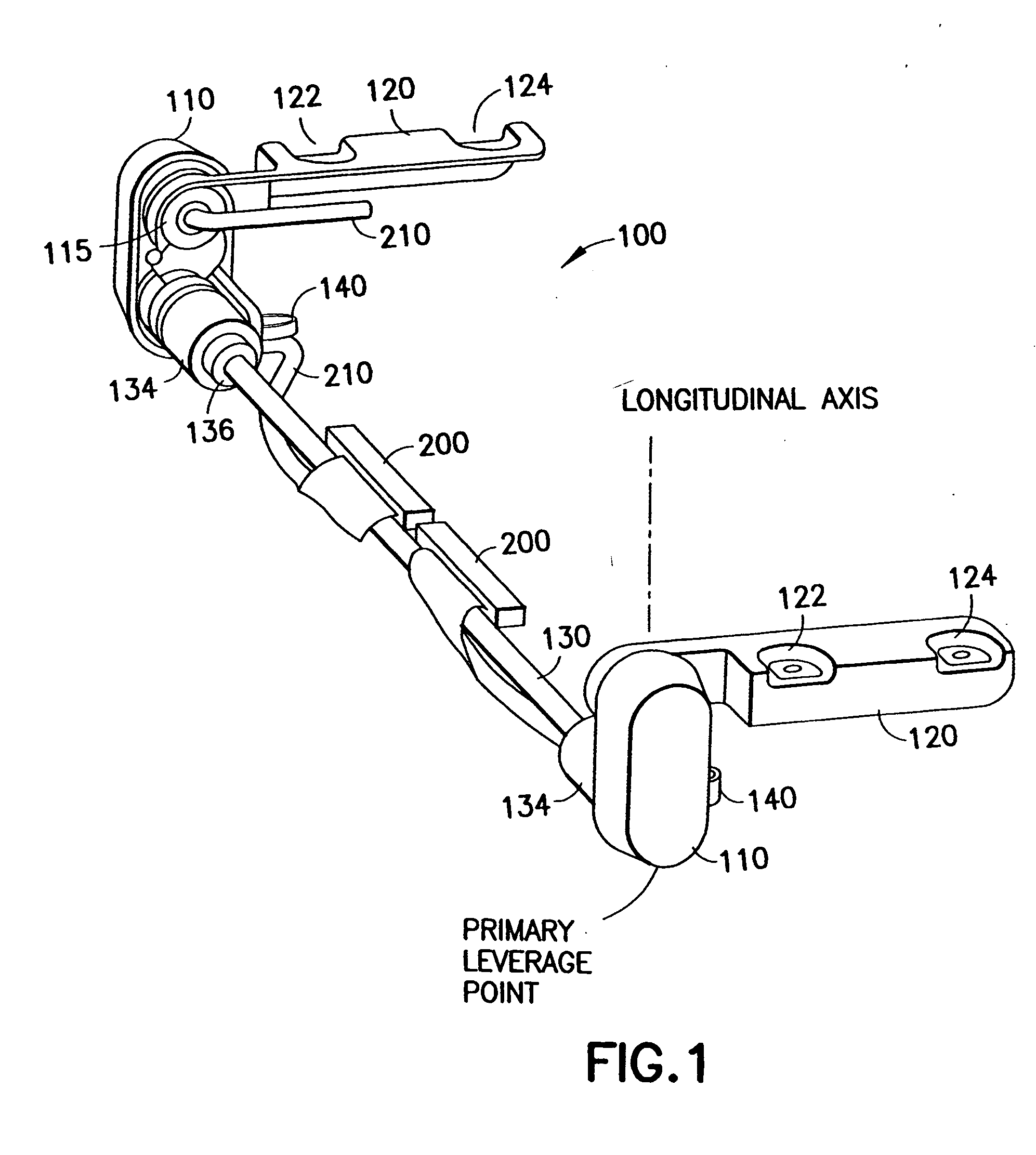
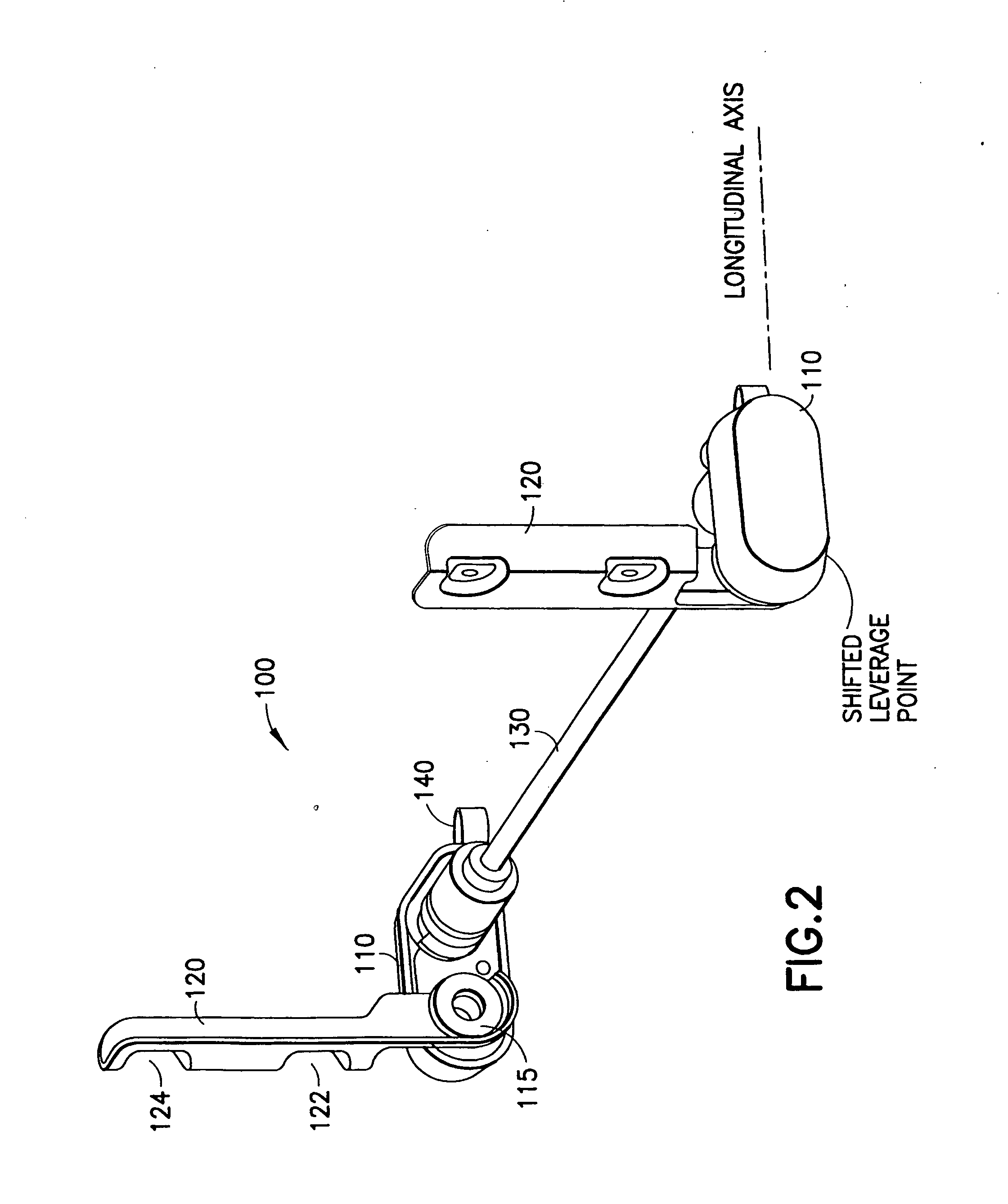
[0011] Using a hinge with two independent rotational axes for rotating the upper device part in relation to the lower device part, the present invention effectively moves the leverage point on the hinge away from the center of gravity of lower part of the device. Because the distance between the center of gravity of the lower part and the leverage point increases, the device is more stable regarding the countering of the center of gravity of the lower part of the device against the center of gravity of the upper part.

Problems solved by technology

When the laptop computer is placed on a flat surface in an open position and the angle between the lid and the engine part is large, say between 120 degrees and 180 degrees, the laptop computer may rock if the lid is heavy as compared to the engine part.
As the display is made larger, the lid becomes heavier and the laptop computer in such an open position becomes less stable.

Method used


Image

  • Double-axis hinge for use in electronic devices
  • Double-axis hinge for use in electronic devices
  • Double-axis hinge for use in electronic devices

Examples


Embodiment Construction

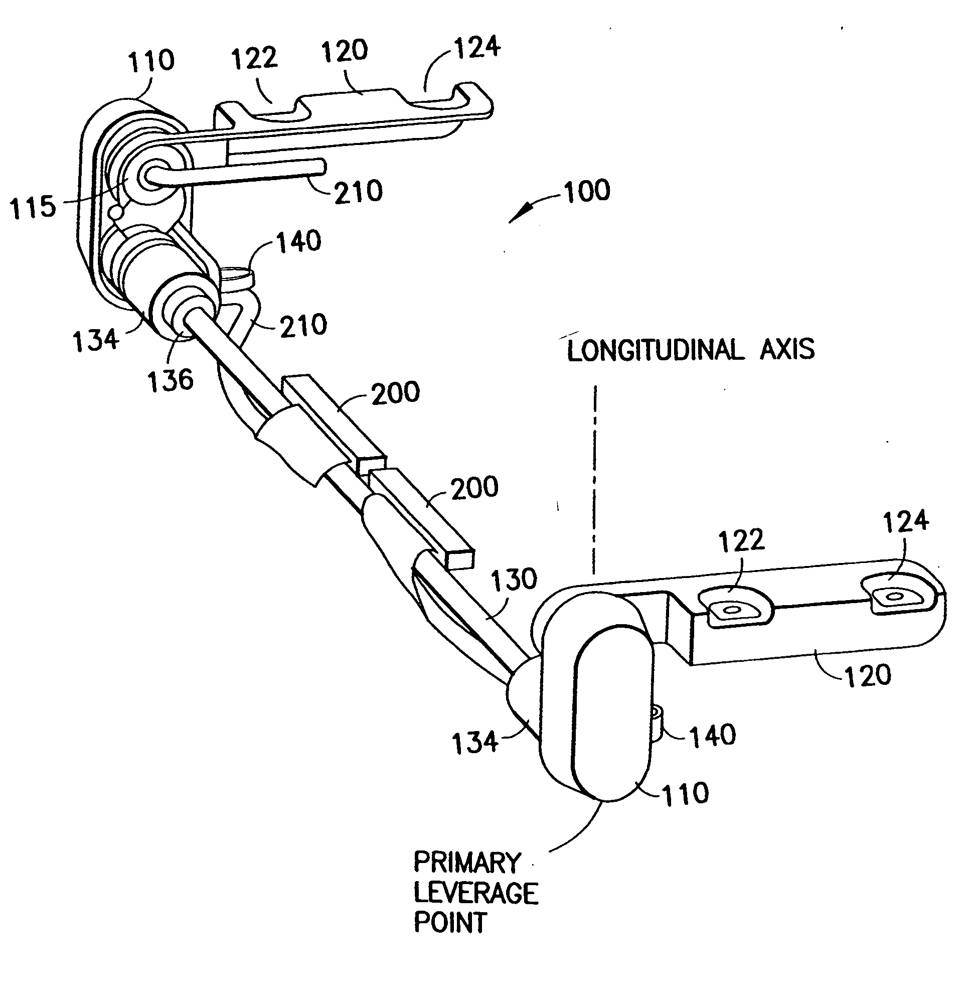
[0029] The hinge, according to the present invention, has two rotational axes. One rotational axis is defined by a shaft connected between two hinge arms. Each hinge arm has a pivot for rotatably mounting a bracket. The pivot on each hinge arm defines another rotation axis. As shown in FIG. 1, the hinge 100 has two hinge arms 110. Each hinge arm has a first section, a second section and a first bracket 120 pivotably mounted at pivot 115 at the first section. The hinge 100 has a shaft 130 mounted between the second sections of the hinge arms 110. The hinge 100 also has two sleeves 134 on opposite ends of the shaft 130 for mounting two second brackets 140. The hinge 100 has two restraining collars 136 to limit the lateral movement of the sleeves 134 along the shaft 130. The hinge is intended for use in an electronic device having an upper part rotatably connected to a lower part (see FIGS. 4a-4j). The first brackets are used for mounting the upper part 10 of the electronic device. For...


PUM


Abstract

A hinge has two hinge arms for rotatably mounting a lower part of an electronic device of a clamshell design at a first rotational axis and for rotatably mounting an upper part of the electronic device at a second rotational axis. When the angle between the lower and second parts is within a first angular range, the hinge arms are rotated against the lower part in order to change the angle and the hinge leverage point is located substantially below the first rotational axis. When the angle is in a second angular range beyond the first angular range, the hinge arms are rotated against the upper part in order to change the angle and to move the leverage point away from the lower part. As such, the stability of the electronic device when the angle is in the second angular range.

Description

FIELD OF THE INVENTION [0001] The present invention relates generally to a foldable electronic device which can be opened to reveal two facing surfaces of two device parts and, more particularly, to a hinge for linking the device parts. BACKGROUND OF THE INVENTION [0002] Foldable electronic devices such as mobile phones, laptop computers, and PDAs comprise two device parts linked by a hinge. The hinge can be a single-axis construction wherein two hinge plates with coupling channels are separately connected to the device parts and a pin is inserted through the coupling channels as a pivot axis to join the two hinge plates. A single-axis hinge can also be constructed with a coil spring wrapped around a pivot pin wherein each end of the coil spring is secured to one device part. [0003] Using a laptop computer as an example, the upper device part is the lid containing a display and the lower device part is the engine part containing the motherboard and the keyboard. When the laptop comp...

Claims


Application Information

Patent Timeline
Patent Type & Authority Applications(United States)
IPC IPC(8): E05D3/06
CPCG06F1/1616Y10T16/547H04M1/022G06F1/1681G06F1/16G06F1/1626
Inventor KOMPPA, KIMMO
Owner NOKIA CORP
Why Eureka
Try Eureka