
Refrigerant measuring and warning device and sensing element thereof

Inactive Publication Date: 2007-10-11
BOUNDLESS LIN
View PDF6 Cites 7 Cited by
  • Summary
  • Abstract
  • Description
  • Claims
  • Application Information

AI Technical Summary

Benefits of technology

[0009]The refrigerant measuring and warning device allows for precise measurement, display, and monitoring of the pressure and temperature of the refrigerant to be detected and can provide multiple sets of reference pressure and temperature that are directly displayed on a display device, for comparison with the detected refrigerant pressure and temperature. Further, the device of the present invention allows for issuance of alarms when the detected pressure and temperature reach / exceed preset thresholds of pressure and temperature. Thus, the filling of the refrigerant in an air conditioner or refrigeration facility can be performed in a more precise and controlled manner. Besides, the problems of errors caused by visual observation of the conventional analog meter can be eliminated.

Problems solved by technology

The meter is an analog device and can only provide a single reading of the detected pressure of the filled refrigerant.
Visual observation of the meter reading is not very precise and can results in significant error.
Further, the conventional meter cannot detect temperature of the filled refrigerant.
In addition, the conventional meter cannot provide references for the detected pressure of the refrigerant, which often causes troubles to the operator in carrying out refrigerant filling and measuring.
This certainly increases the costs.
Besides, the problems of incorrect reading of the meters mentioned above also induce impreciseness for the operation of refrigerant filling that may be very important in certain applications.

Method used


Image

  • Refrigerant measuring and warning device and sensing element thereof
  • Refrigerant measuring and warning device and sensing element thereof
  • Refrigerant measuring and warning device and sensing element thereof

Examples


Embodiment Construction

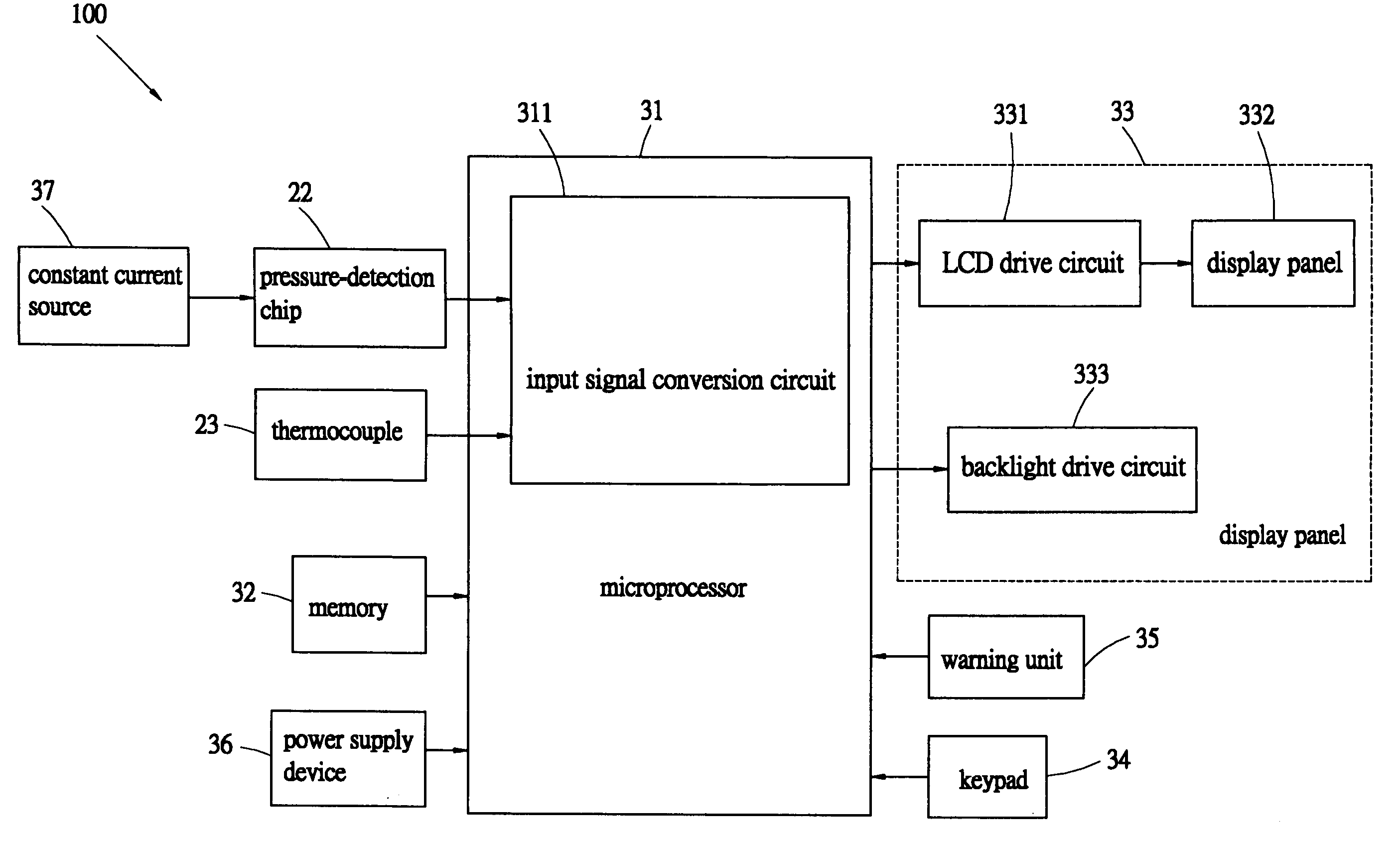
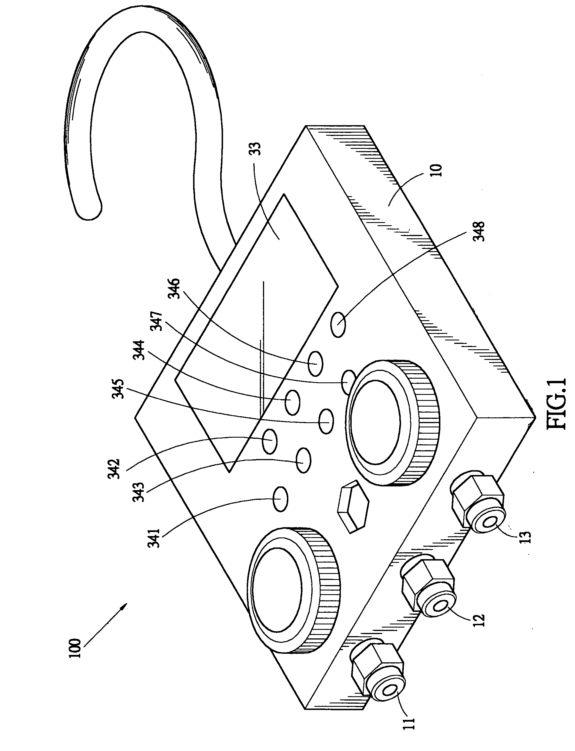
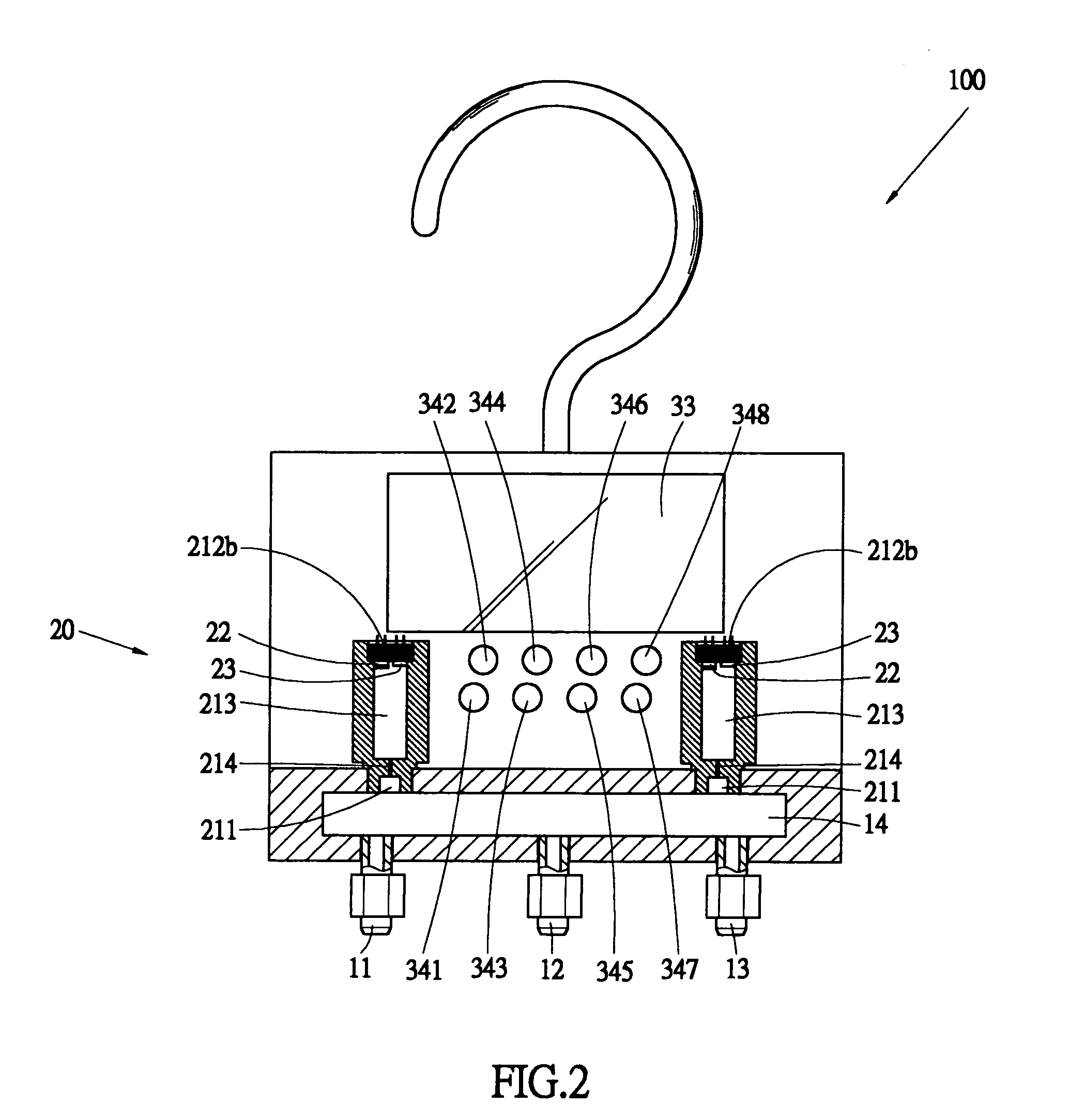
[0021]With reference to the drawings and in particular to FIGS. 1 and 2, a refrigerant measuring and warning device constructed in accordance with the present invention, generally designated with reference numeral 100, comprises a casing 10, at least one sensing element 20, and a detection circuit 30. The casing 10 is provided with a plurality of detection connectors 11, 12, 13, which provide connection with refrigerant to be detected. The detection connectors 11, 12, 13 are connected together with a connection conduit 14.

[0022]Also referring to FIGS. 3 and 4, the sensing element 20, which is constructed in accordance with a first embodiment of the present invention, is shown. The sensing element 20 comprises an enclosure 21, a pressure detection chip 22, and a thermocouple 23. An end of the enclosure 21 forms a connector 211 and an opposite end forms an inner-threaded opening 212. The connector 211 connects to the connection conduit 14 that is arranged inside the casing 10. In the ...


PUM


Abstract

A refrigerant measuring and warning device includes a casing, at least one sensing element, and a detection circuit. The casing forms connectors, which are connected together by a conduit, to selectively connect to sources of refrigerant to be detected. The sensing element has an enclosure forming a connector at an end for connection with the conduit and an interior chamber communicating the connector via a pressure-dropping necked passage, a pressure detection chip and a thermocouple arranged at a top of the chamber for detecting pressure and temperature of the refrigerant to be detected. The detection circuit is housed in the casing and stores multiple sets of reference temperature and pressure for different type of refrigerants for comparison with the detected pressure and temperature, both data being displayed on a display device for visual observation and comparison. The detection circuit receives settings of alarm thresholds for the detected pressure and temperature via a keypad whereby a warning unit may issue a warning sound or voice alarm when the detected pressure and temperature reach / exceed the thresholds.

Description

BACKGROUND OF THE INVENTION[0001]1. Field of the Invention[0002]The present invention generally relates to a refrigerant measuring and warning device and a sensing element thereof, and in particular to a refrigerant measuring and warning device that features comparison and detection of refrigerant pressure and temperature, digital display, and alarm by exceeding of thresholds.[0003]2. The Related Arts[0004]Air conditioner and refrigeration facility provides air conditioning and refrigeration by means of refrigerant that is filled in and circulates through the air conditioner or the refrigeration facility through compression-expansion cycles. Conventionally, a meter is used to detect the pressure of the refrigerant filled into the air conditioner or refrigeration system. The meter is an analog device and can only provide a single reading of the detected pressure of the filled refrigerant. Visual observation of the meter reading is not very precise and can results in significant error...

Claims


Application Information

Patent Timeline
IPC IPC(8): F25B45/00
CPCG01L19/0092G01K13/02
Inventor CHEN, CHIANG KAO
Owner BOUNDLESS LIN
Learn More