
Lighting head assembly with integrated heat sink

a heat sink and lighting head technology, applied in the direction of lighting and heating apparatus, semiconductor devices for light sources, coupling device connections, etc., can solve the problems of non-uniform illumination field, device production unacceptable, non-uniform light image in the far field of lighting devices, etc., to facilitate compact nature, facilitate the effect of further incorporating the assembly, and precise and controlled manner

Active Publication Date: 2006-03-07
NITE IZE INC
View PDF3 Cites 49 Cited by
  • Summary
  • Abstract
  • Description
  • Claims
  • Application Information

AI Technical Summary

Benefits of technology

The present invention provides a compact lighting assembly that includes a high brightness light source such as an LED. The assembly includes a tubular receiver sleeve that centers the LED and channels the light forward. The receiver also acts as a heat sink to transfer the heat generated by the LED away from the LED and the driver circuitry. The assembly can be incorporated into various lighting devices such as flashlights, providing precise and controlled beam control. The assembly process is streamlined and the precision of the finished device is greatly improved. The invention also includes a novel construction for insuring that contact to the power source will only occur if the battery is installed in the proper orientation. The invention offers improved light capture and transfer, as well as integrated voltage polarity protection for the LED driver circuitry.

Problems solved by technology

In general, these smooth reflector type assemblies simply re-image the light source into the far field of the device and create a poorly distributed, non-uniform illuminated field.
While this shape reduces the direct re-imaging of the light source, this solution simply smears the image taken from the far field of the light source and projects that smeared image in the far field of the flashlight beam thereby still providing a non-uniform light image in the far field of the lighting device.
These devices also produce an unacceptable result as they capture the far field image from a plane projected in front of the LED package and simply enlarge the LED image and then reflects that image in a reversed pattern in the flashlight beam far field.
Further, because the LED lighting elements generate a great deal of heat, a heat dissipation path must be provided as well.
All of these factors combined in the prior art to prevent the design of a compact lighting assembly that could incorporate a single high brightness LED.
The drawback is that this circuitry is extremely sensitive to reversed polarity.

Method used


Image

  • Lighting head assembly with integrated heat sink
  • Lighting head assembly with integrated heat sink
  • Lighting head assembly with integrated heat sink

Examples


Embodiment Construction

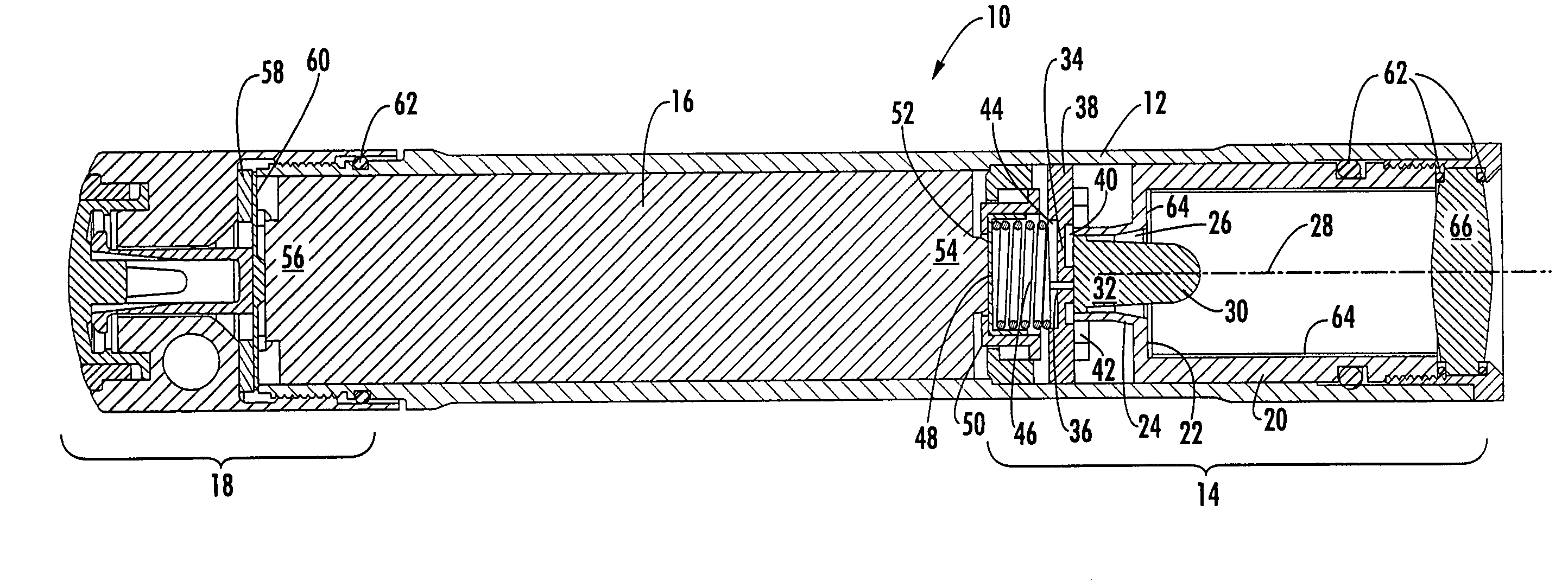
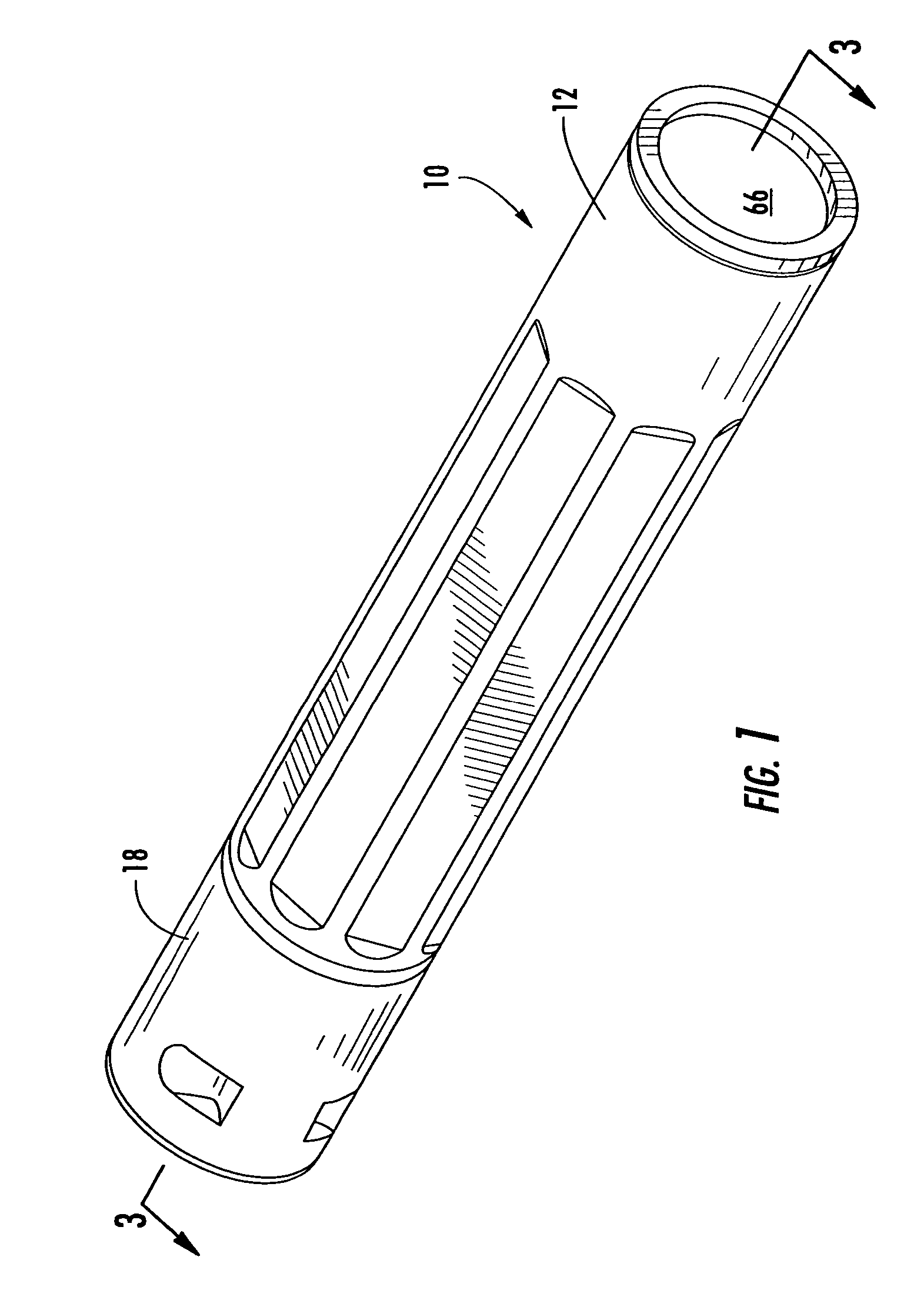
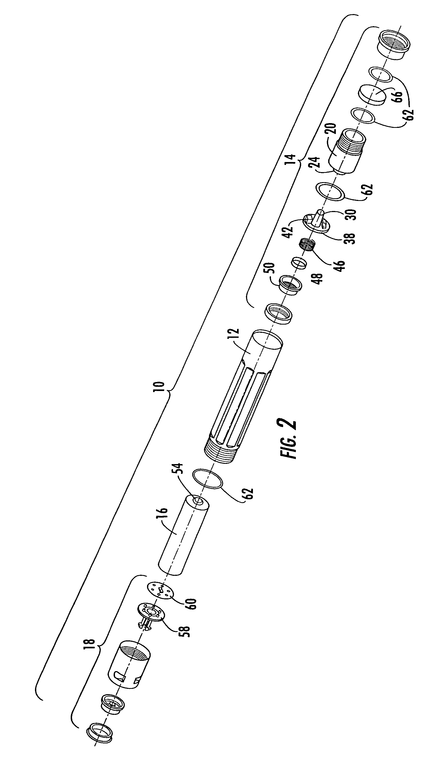
[0022]Referring now to the drawings, the lighting head assembly of the present invention is shown and illustrated in the form of a compact flashlight that is generally illustrated and indicated at 10 in FIGS. 1–5. As stated above while the lighting head assembly is shown, for the purposes of the preferred embodiment, as being incorporated into a compact flashlight 10 assembly it can be appreciated by one skilled in the art that the present disclosure anticipated the lighting head being utilized in a variety of suitable assemblies. By way of example the head assembly of the present invention can be easily and efficiently incorporated into architectural lighting assemblies, general task lighting assemblies or automotive lighting assemblies and still remain within the spirit and scope of the present disclosure. As can be seen in FIG. 1 a flashlight 10 is shown that includes a tubular housing 12 with the lighting head assembly 14 of the present invention installed into one end thereof. ...


PUM


Abstract

A novel lighting assembly that incorporates a high brightness light emitting diode (LED) in a compact assembly for further integration into a lighting device is provided. The lighting head assembly of the present invention provides several novel aspects that are all closely integrated to provide a unique assembly for incorporating a high brightness LED into a lighting device. In particular, the head assembly utilizes a receiver sleeve that includes a tail portion which surrounds the output end of the LED thereby isolating the LED and capturing both the conductive and radiant waste heat emitted by the LED to further dissipate the captured heat out of the assembly.

Description

CROSS-REFERENCE TO RELATED APPLICATIONS[0001]This application is related to and claims priority from earlier filed provisional patent application No. 60 / 437,810, filed Jan. 3, 2003.BACKGROUND OF THE INVENTION[0002]The present invention relates to a new lighting head assembly for use in lighting devices such as commercial and residential lighting fixtures, flashlights and miniature flashlights. More particularly, the present invention relates to compact and efficient lighting head assemblies for use with lighting devices of the type employing a high brightness light emitting diode (LED) to provide a smooth uniform spotlight beam having sharp edges.[0003]Most commercially available lighting devices are designed to provide an on-axis, high intensity peak in their beam distribution as is typically found in flashlights with smooth reflectors or specialty architectural spotlights such as picture lights. In other words, most conventional lighting assemblies provide a central spot that is h...

Claims


Application Information

Patent Timeline
Patent Type & Authority Patents(United States)
IPC IPC(8): B60Q1/06F21V29/00F21L4/02F21V5/04F21V23/04F21V31/00H01R33/09
CPCF21L4/027F21V5/04F21V23/0414F21V29/004F21V29/74F21V31/00F21Y2101/02H01R33/09Y10S362/80F21Y2115/10F21V31/005
Inventor GALLI
Owner NITE IZE INC
Learn More