

Decoding device and method
a decoding device and decoding method technology, applied in the field of decoding devices, can solve the problems of a lot more complicated a substantial substandard advantage of soft decision decoding devi
- Summary
- Abstract
- Description
- Claims
- Application Information
AI Technical Summary
Problems solved by technology
Method used
Image

Examples
first embodiment
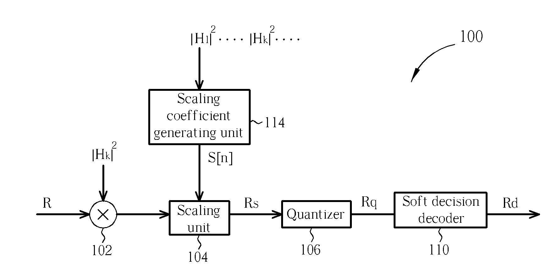
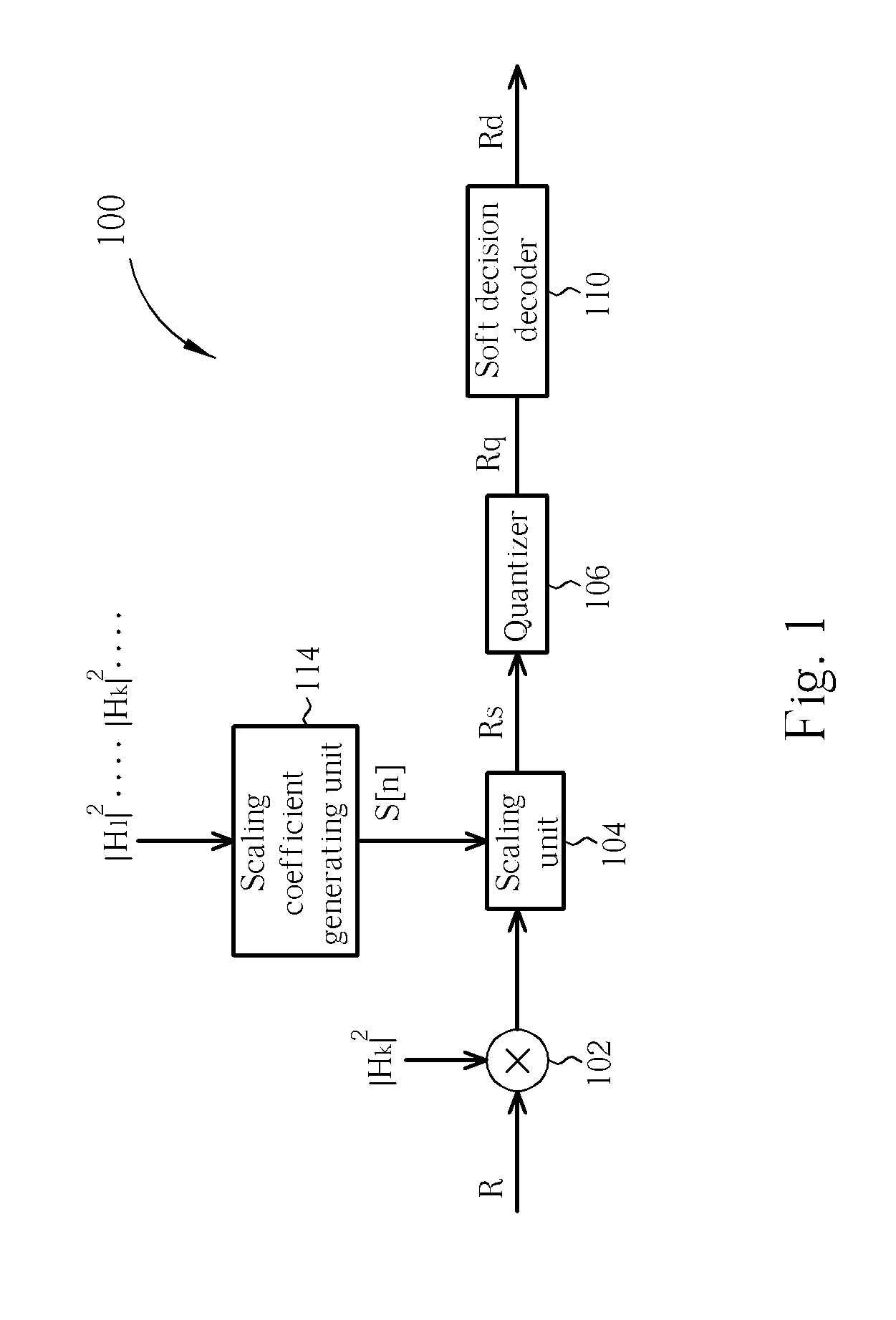
[0016]Please refer to FIG. 1. FIG. 1 is a diagram illustrating a decoding device 100 according to the present invention. In this embodiment, the decoding device 100 is applied in a multi-tone system, such as an orthogonal frequency division multiplexing (OFDM) system, and a received signal R is a multi-tone signal. Thus the received signal R contains a plurality of sub-data respectively carried by various sub-carriers. Those skilled in the art will understand that the embodiment of the present invention described in the following can also be applied in other types of communications systems, be it wired or wireless, and is not limited to an OFDM system. In FIG. 1, the decoding device 100 comprises a channel response compensation unit 102, a scaling unit 104, a quantizer 106, a soft decision decoder 110, and a scaling coefficient generating unit 114. Firstly, the channel response compensation unit 102, according to channel response |Hk|2 of each sub-carrier, adjusts the amplitude of t...
second embodiment
[0032]Please refer to FIG. 3. FIG. 3 is a diagram illustrating a decoding device 300 according to the present invention. In FIG. 3, the decoding device 300 comprises a channel response compensation unit 302, a scaling unit 304, a quantizer 306, a soft decision decoder 310, an error detecting unit 312, and a scaling coefficient generating unit 314. Except for the error detecting unit 312 and the scaling coefficient generating unit 314, the parts bearing the same name in FIG. 3 and FIG. 1 are configured the same and operate in the same manner, therefore further detailed descriptions regarding those parts in FIG. 3 are herein omitted. After the soft decision decoder 310 decodes the quantized signal Rq to generate the decoded signal Rd, the error detecting unit 312 further estimates a bit error rate BER of the decoded signal Rd, and the scaling coefficient generating unit 314 determines the most suitable scaling coefficient S[n] according to the numerous bit error rates BER respectively...
third embodiment
[0048]Please refer to FIG. 5. FIG. 5 is a diagram illustrating a decoding device 500 according to the present invention. In FIG. 5, the decoding device 500 comprises a channel response compensation unit 502, a scaling unit 504, a quantizer 506, a probability calculating unit 508, a soft decision decoder 510, and a scaling coefficient generating unit 514. Except for the probability calculating unit 508 and the scaling coefficient generating unit 514, the parts bearing the same name in FIG. 5 and FIG. 1 are configured the same and operate in the same manner, therefore further detailed descriptions regarding those parts in FIG. 5 are herein omitted. In this embodiment, the probability calculating unit 508 is used to gather statistics of the probability P of the plurality of sub-data, which correspond to the quantized signal Rq, being equal to zero. The scaling coefficient generating unit 514 generates the scaling coefficient S[n] according to the probability P corresponding to a plural...
PUM
 Abstract
Description
Claims
Application Information