Motor drive circuit for driving a synchronous motor

a technology of synchronous motors and motor drives, applied in the direction of motor/generator/converter stoppers, electronic commutators, dynamo-electric converter control, etc., can solve the problems of high cost and increase in circuit scal

Active Publication Date: 2011-06-30
SEMICON COMPONENTS IND LLC
View PDF4 Cites 20 Cited by
  • Summary
  • Abstract
  • Description
  • Claims
  • Application Information

AI Technical Summary

Problems solved by technology

In the method (1), the circuit scal...

Method used


Image

  • Motor drive circuit for driving a synchronous motor
  • Motor drive circuit for driving a synchronous motor
  • Motor drive circuit for driving a synchronous motor

Examples


Embodiment Construction

[0024]The invention will now be described by reference to the preferred embodiments. This does not intend to limit the scope of the present invention, but to exemplify the invention.

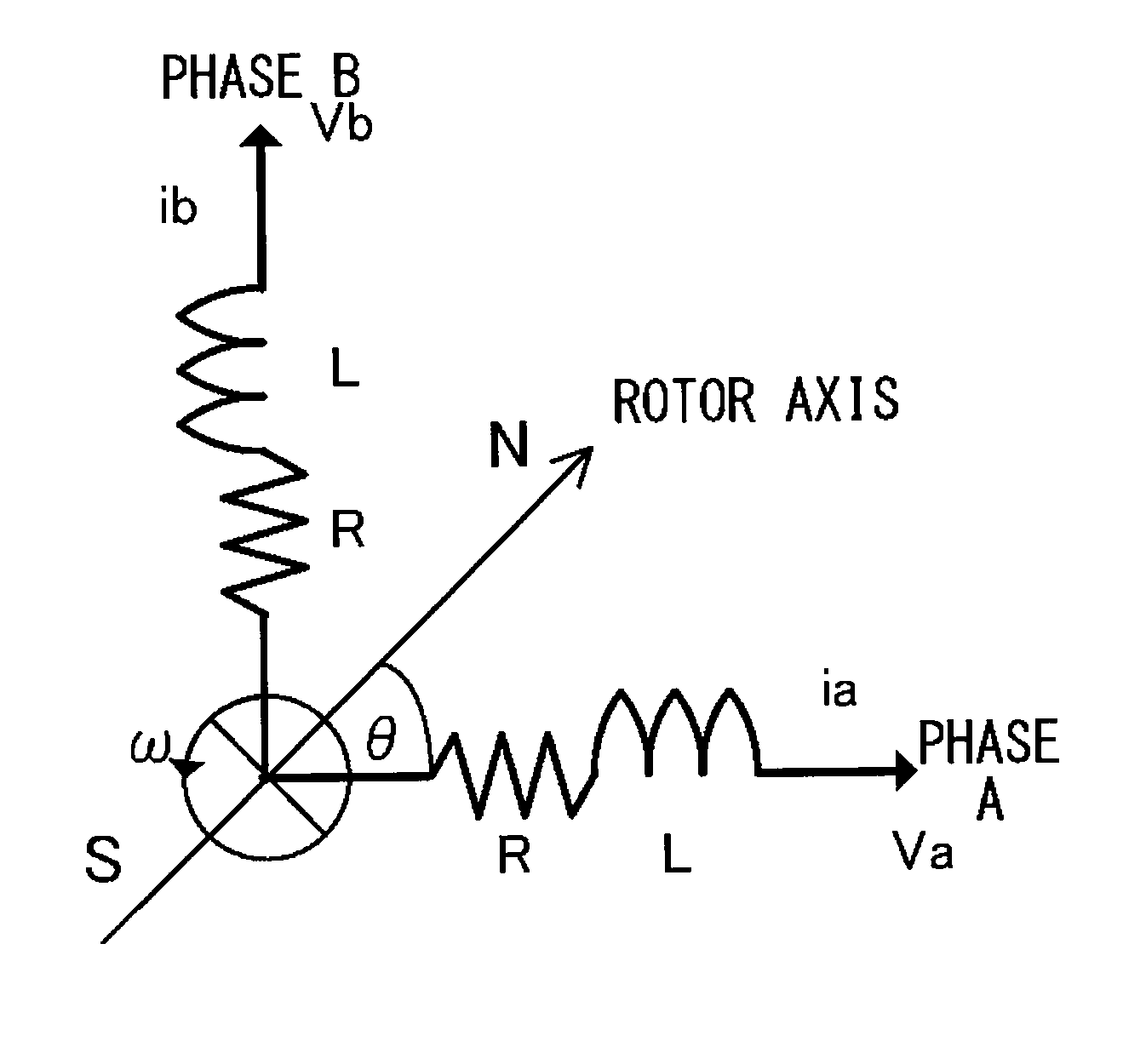
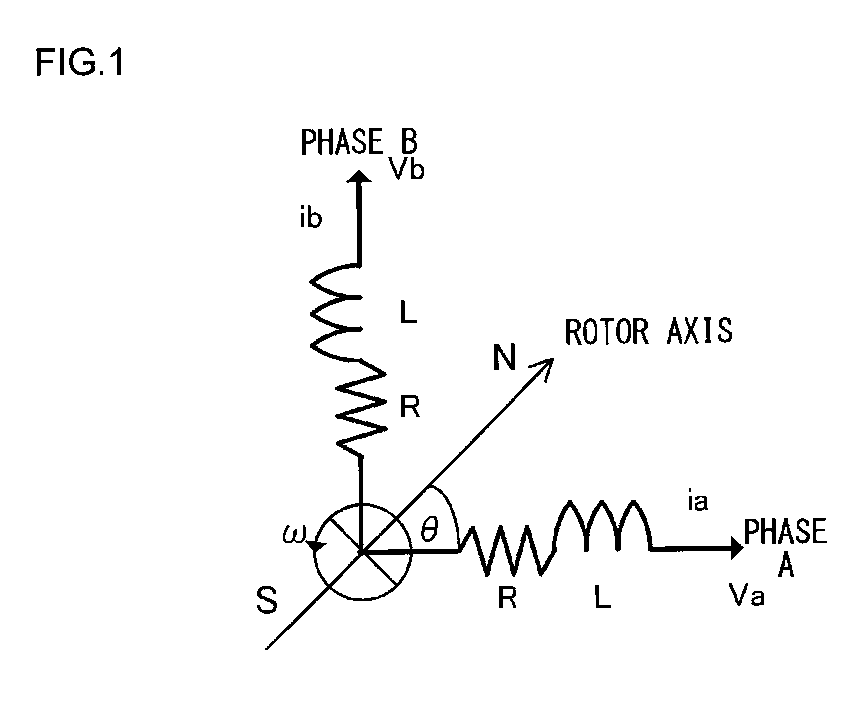
[0025]A description will be given of knowledge gained by the inventor of the present invention and used for the embodiments of the present invention before a specific description of the embodiments. The knowledge specifies a relation between a stator and a rotor included in a motor. FIG. 1 is an illustration for explaining a relation between a stator and a rotor in a 2-phase permanent magnet synchronous motor (PMSM). Each symbol denoted in FIG. 1 is defined as follows.

[0026]L:=Inductance of each phase.

[0027]ia, ib:=Current of each phase.

[0028]R:=Direct-current (DC) resistance DCR of each stator.

[0029]Va, Vb:=Voltage of each phase.

[0030]θ:=Angle formed between a rotor axis and a phase-A axis.

[0031]ω:=Angular velocity of a rotor (dθ / dt).

[0032]Though the rotor is a permanent magnet, a phase-A axis compone...


PUM


Abstract

A coil current detector detects a current component flowing through a coil. A scaling unit scales a drive signal. An induced voltage component extraction unit extracts an induced voltage component by removing the drive signal, scaled by the scaling unit, from the coil current component detected by the current detector. A phase difference detector detects a phase difference between the phase of the drive signal and that of the induced voltage component. A signal adjustment unit adjusts the drive signal so that the phase difference detected by the phase difference detector can be brought close to a target phase difference.

Description

CROSS-REFERENCE TO A RELATED APPLICATION[0001]This application is based upon and claims the benefit of priority from the prior Japanese Patent Application No. 2009-297574, filed on Dec. 28, 2009, the entire contents of which are incorporated herein by reference.BACKGROUND OF THE INVENTION[0002]1. Field of the Invention[0003]The present invention relates to a motor drive circuit for driving a synchronous motor.[0004]2. Description of the Related Art[0005]There are various kinds of synchronous motors. For example, known synchronous motors are a surface permanent magnet synchronous motor (SPMSM), a permanent magnet (PM) type stepping motor, a variable reluctance (VR) type stepping motor, a hybrid (HB) type stepping motor, a brushless DC motor (BLDCM) and the like. As methods for detecting the rotational position of a synchronous motor, there are a method using a sensor and a method without using the sensor.[0006]As the method without using the sensor, there is a method using the induct...

Claims


Application Information

Patent Timeline
IPC IPC(8): H02P6/18H02P8/14H02P8/12H02P21/14H02P21/18H02P21/24H02P23/14H02P25/04H02P27/06H02P27/08
CPCH02P8/14H02P6/182
Inventor TAKAI, KAZUMASA
Owner SEMICON COMPONENTS IND LLC
Why Eureka
Try Eureka