Ink cartridges, printers and methods for mounting such ink cartridges to such printers

a technology for ink cartridges and printers, which is applied in the field of methods and systems for mounting ink cartridges to ink cartridge holders, ink cartridges, inkjet printers, etc., and can solve problems such as ink leakage from nozzles, and excess ink collecting on the ends of nozzles

Inactive Publication Date: 2007-10-11
BROTHER KOGYO KK
View PDF2 Cites 28 Cited by
  • Summary
  • Abstract
  • Description
  • Claims
  • Application Information

AI Technical Summary

Benefits of technology

[0010]According to an embodiment of the present invention, a method for mounting an ink cartridge, the ink cartridge comprising a case having a first and second opening formed therethrough and an ink chamber formed within the case, comprises dispensing ink from an interior of the ink chamber to an exterior of the ink chamber via the first opening, selectively creating a seal between the first opening and a joint portion of an ink cartridge holder after dispensing ink from the interior of the ink chamber to the exterior of the ink chamber via the first opening, and placing the ink chamber and an exterior of the case in fluid communication via the second opening.
[0011]According to another embodiment of the present invention, an ink cartridge comprises a case having a first opening and a second opening formed therethrough, a partition wall disposed with in the case, and a moveable member disposed within the air chamber. The case and the partition wall define an ink chamber configured to store an ink and an air chamber therebetween, the partition wall separates the ink chamber from the air chamber, and the ink chamber is configured to be in fluid communication with the air chamber via the second opening. The air chamber is configured to guide the moveable member between a first position and a second position within the air chamber. When the moveable member is in the first position, the moveable member prevents fluid communication between the ink chamber and an exterior of the case via the second opening, and the ink is dispensed from an interior of the ink chamber to an exterior of the ink chamber via the first opening. When the moveable member is in the second position, the ink chamber and the exterior of the case are in fluid communication via the second opening.
[0012]According to still another embodiment of the present invention, an inkjet printer comprises an ink cartridge holder configured to removably mount an ink cartridge, and a recording head connected to a joint portion. The ink cartridge comprises a case having a first opening and a second opening formed therethrough, a partition wall disposed within the case. The case and the partition wall define an ink chamber configured to store an ink and an air chamber therebetween, the partition wall separates the ink chamber from the air chamber, and the ink chamber is in fluid communication with the air chamber. The ink cartridge holder comprises a joint portion configured to selectively create a seal with the first opening, and a moveable member configured to move from a first position to a second position when the ink cartridge is mounted to the ink cartridge holder. When the moveable member is in the first position, the moveable member prevents fluid communication between the ink chamber and the air chamber, and the ink is dispensed from an interior of the ink chamber to an exterior of the ink chamber via the first opening, and when the moveable member is in the second position, the ink chamber and the air chamber are in fluid communication via the second opening.

Problems solved by technology

When the known ink cartridge mounted in the ink cartridge holder is replaced with a new ink cartridge, ink may leak from nozzles of a recording head of the inkjet printer, and the excess ink may collect on the ends of the nozzles.
This air pressure may force the ink through the recording head nozzles, and may cause ink to leak from the nozzles.
Pressure may be generated within the ink passages, and the menisci of ink formed within the nozzles may be damaged as a result of this pressure, because the menisci of ink formed within the nozzles is more fragile than menisci of ink formed within the filter's pores.
Once the menisci of ink formed within the nozzles are damaged, the ink may leak from the nozzles.
Ink leaking from the nozzles creates a number of potential complications with the printing system.
This transferred ink eventually may adhere to the recording medium via the parts of the inkjet printer, which may diminish print quality and cause print errors.
Nevertheless, in the known inkjet cartridge holder, once the ink supply hole is connected to the joint portion and the ink passage becomes airtight, air caught between the ink in the ink supply hole and the ink in the joint portion cannot escape to the outside.

Method used


Image

  • Ink cartridges, printers and methods for mounting such ink cartridges to such printers
  • Ink cartridges, printers and methods for mounting such ink cartridges to such printers
  • Ink cartridges, printers and methods for mounting such ink cartridges to such printers

Examples


Embodiment Construction

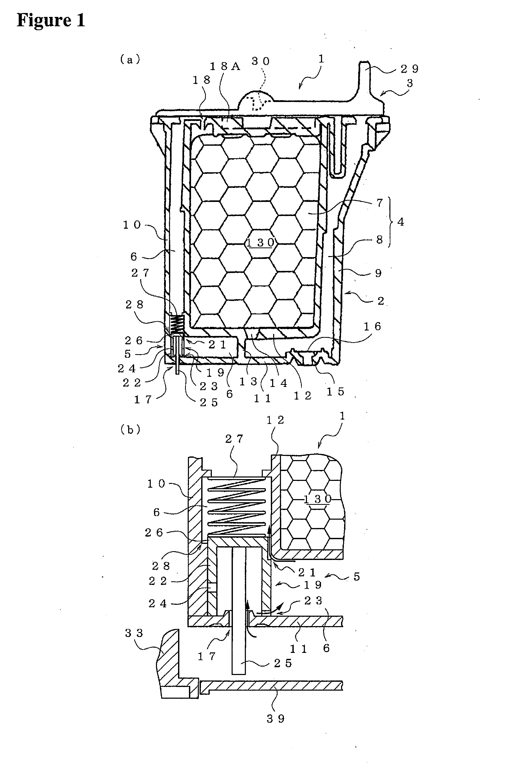
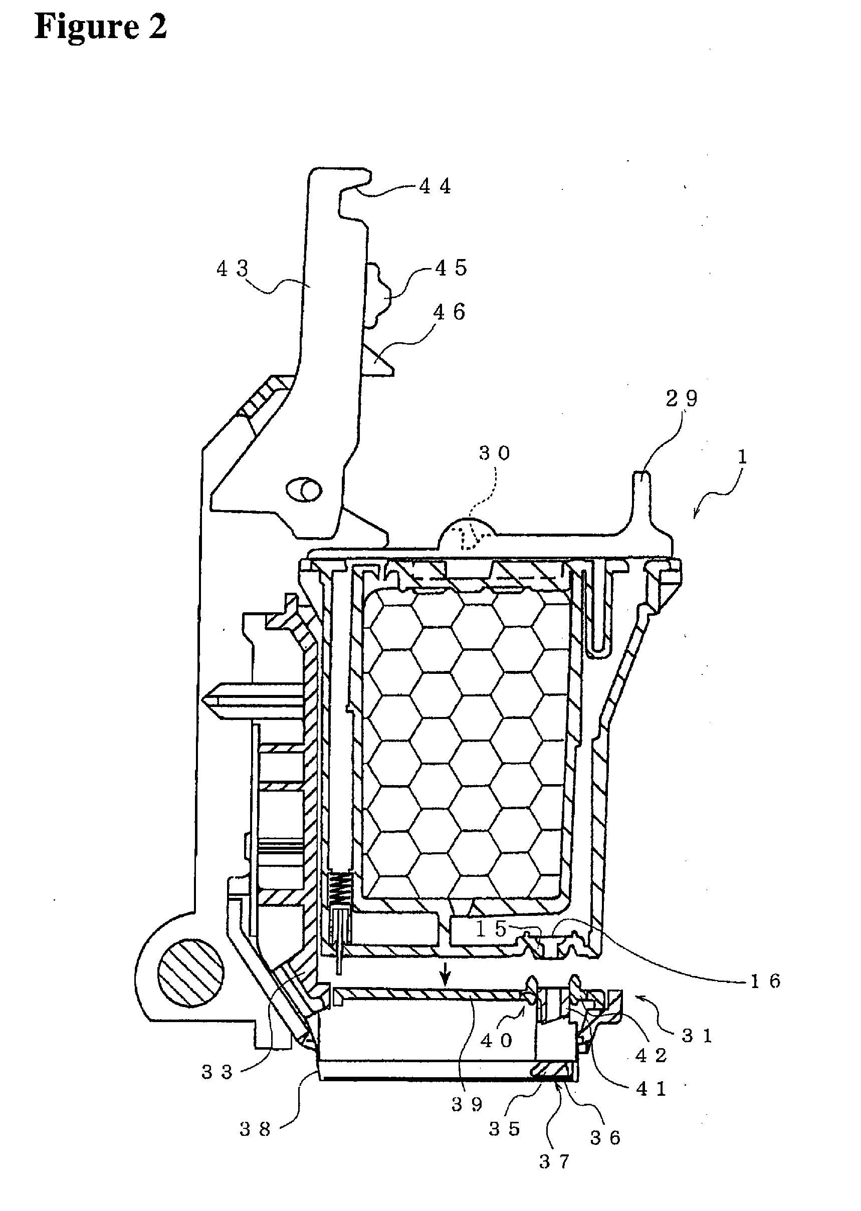
[0027]Embodiments of the present invention, and their features and advantages, are understood by referring to FIGS. 1-9, with like numerals being used for like corresponding parts in the various drawings.

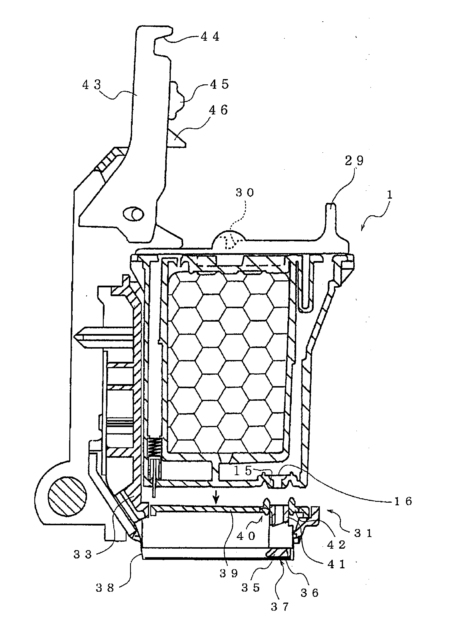
[0028]Referring to FIGS. 1(a) and 1(b), according to an embodiment of the present invention, an ink cartridge 1 may comprise a box-shaped case 2 and a lid 3 attached to the top of box-shaped case 2. In an embodiment of the present invention, both case 2 and lid 3 may comprise synthetic resin or any similar substance. Ink cartridge 1 may comprise an ink chamber 4 formed within case 2 and ink may be stored within ink chamber 4.

[0029]In an embodiment of the present invention, case 2 may be a substantially hexahedron case comprising a case front wall 9, a case back wall 10 opposite to case front wall 9, a case top wall 18A, a case bottom wall 11 opposite to case top wall 18A, and two case side walls opposite to each other (not shown). Nevertheless, case 2 may have any geometric shape. T...


PUM


Abstract

The present invention relates to a method for mounting ink cartridges, an ink cartridge holder, and an inkjet printer. The method includes preventing an ink chamber and an exterior of the ink cartridge case from being in fluid communication, dispensing ink from an interior of the ink chamber to an exterior of the ink chamber via an opening, moving a moveable member into a second position after the moveable member has been in the first position, placing the ink chamber and the air chamber in fluid communication. The ink cartridge holder includes a case having a first opening and a second opening, a partition wall, and a moveable member. The inkjet printer includes an ink cartridge holder and a recording head, the ink cartridge holder having a joint portion and a moveable member.

Description

CROSS-RELATED APPLICATION[0001]The present application claims priority from Japanese Patent Application No. JP-2006-103797, which was filed on Apr. 5, 2006, the disclosure of which is incorporated herein by reference in its entirety.BACKGROUND OF THE INVENTION[0002]1. Field of the Invention[0003]The present invention relates generally to methods and systems for mounting an ink cartridge to an ink cartridge holder, to ink cartridges, and to inkjet printers. In particular, the present invention is directed towards ink cartridges comprising a case having a first opening and a second opening, a partition wall defining an ink chamber and an air chamber, and a moveable member disposed within the air chamber. The present invention also is directed towards an inkjet printer using a similar type of cartridge, and a method for mounting the ink cartridge on the inkjet printer.[0004]2. Description of Related Art[0005]A known ink cartridge in an inkjet printer is mounted to an ink cartridge hold...

Claims


Application Information

Patent Timeline
Patent Type & Authority Applications(United States)
IPC IPC(8): B41J2/175
CPCB41J2/17513B41J2/17526B41J2/1752
Inventor YAMADA, TAKAHIRO
Owner BROTHER KOGYO KK
Why Eureka
Try Eureka