Fastening mechanism

a technology of fastening mechanism and clamping rod, which is applied in the direction of electrical apparatus construction details, electrical apparatus casings/cabinets/drawers, support structure mounting, etc., can solve the problems of affecting inconvenience in disassembly, and the likelihood of flip loosening problems, so as to increase the manufacturing cost, reduce the cost, and reinforce the stability and balance of the coupling

Inactive Publication Date: 2007-10-11
INVENTEC CORP
View PDF14 Cites 7 Cited by
  • Summary
  • Abstract
  • Description
  • Claims
  • Application Information

AI Technical Summary

Benefits of technology

[0012] In view of the above-mentioned problems of the prior art, it is a primary objective of the present invention to provide a fastening mechanism that helps to rapidly fasten and disassemble a functional board onto and from an electronic device.
[0013] Another objective of the present invention to provide a fastening mechanism that helps to fixedly fasten a functional board onto an electronic device.
[0014] Still another objective of the present invention is to provide a fastening mechanism that helps to reduce the manufacturing cost required for fastening a functional board onto an electronic device.
[0017] Preferably, said pinch unit is a block body having a groove formed thereon towards the direction of the functional board for embedding said functional board therein. Said pinch unit further includes a strengthening portion to reinforce the stability and balance of the coupling of said pinch unit with said functional board, wherein said strengthening portion is composed of a plurality of protrusions correspondingly disposed on both sides of said groove. Said elastic unit can be a plurality of spring arms formed in a direction away from said functional board, and further includes a pressing portion formed on an end of said elastic unit that can be disposed flatly against said cover board to balance the pressure of said elastic unit. Said pinch unit and said elastic unit are made of an insulating material, and said elastic unit is integrally formed in said pinch unit.
[0018] Compared to the prior techniques that require specific skills, cause inconvenience, and increase the manufacturing cost as mentioned above, the fastening mechanism proposed by the present invention can improve on the prior art by using a pinch unit to pinch-hold one side of the functional board, having the cover board press the elastic unit to fasten the board onto circuit boards of an electronic device. And as the fastening mechanism can be integrally formed without requiring extra processing on electronic components or devices, thereby desirably reducing the cost as a result. Moreover, the fastening mechanism according to the invention can replace the use of screws to fixedly and rapidly fasten a PCI card onto a mainframe board, and also is easy to disassemble when required. Therefore, the present invention yields advantages over the prior part as it is easy and fast to install and disassemble, is cost-effective, and has passed the drop tests to be a highly reliable product having industrial value.

Problems solved by technology

With the increasing powerful functions of the server installation, more and more electrical components are required to be configured in electronic devices, which in turn necessitates more circuits to be disposed and connected to the circuit board, including the heat-dissipating fan additionally adapted for increasing the performance of an electronic device, leading to a crowding and disorganizing configuration and causing inconvenience in disassembly due to the crowded circuits disposed in an electronic device.
However, the bridge connecting board used for electrically connecting the mainframe board and integrated circuits is only electrically connected, a flip loosening problem is likely to occur in drop tests and shock tests.
However, in practical applications, it is often cumbersome and difficult to install a bridge connecting board to an electronic device, for a user is required to exert an even force on both ends of the bridge connecting board so as to install the bridge connecting board onto the electrical connecting grooves of the mainframe board 11 and the integrated circuit board 12.
It takes time and repeated operations to be able to fixedly couple the related hook 110 with the positioning opening 101 and is inefficient and inconvenient to use.
In addition, there also exist a cost concern in the fabrication of a conventional fastening mechanism for a bridge connecting board.
Further, the disposal of the related hook 110 would undesirably occupy the valuable space on the mainframe board 11 and the integrated circuit board 12.
Particularly when replacing the bridge connecting board 10, it is necessary to move the related hook 110 outwardly and that necessitates reservation of a space on the outside of the electrical connecting groove, adversely affecting the flexibility in using the space on the mainframe board 11 and the integrated circuit board 12.
Moreover, the fastening of memories (any one of S-RAM, D-RAM, SD-RAM, DDR-RAM, DDR2-RAM, RAMBUS) also share the same problem as described above.
For example, the fastening method of a PCI card typically has one end thereof being affixed by screws, which often causes the PCI card unable to be easily inserted into the electrical inserting groove of the mainframe board, for if the screw is fastened too tight the other end may raise up whereas if too loose, it tends to sway.

Method used


Image

  • Fastening mechanism
  • Fastening mechanism
  • Fastening mechanism

Examples


Embodiment Construction

[0024] The following illustrative embodiments are provided to illustrate the disclosure of the present invention, these and other advantages and effects being readily understood by those in the art after reading the disclosure of this specification. The present invention can also be performed or applied by other differing embodiments. The details of the specification may be modified on the basis of different points and applications, and numerous modifications and variations can be devised without departing from the spirit of the present invention.

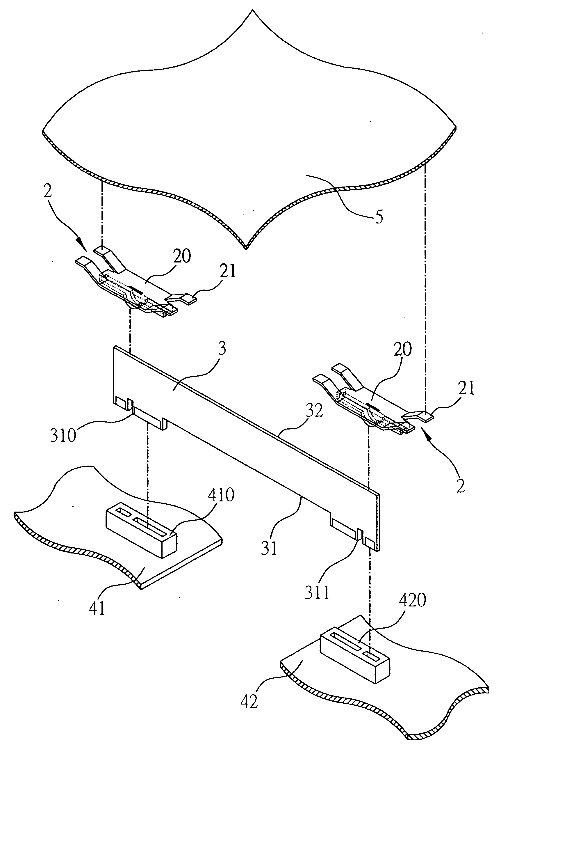
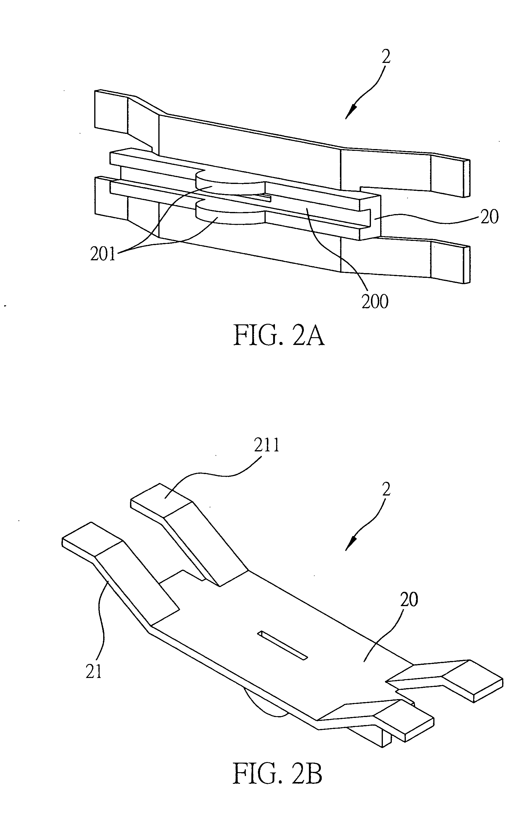
[0025]FIGS. 2 through 4 are drawn according to the preferred embodiment of the fastening mechanism of a functional board of the present invention. Note that the fastening mechanism described in the following embodiment can be applied to any one of the functional boards including a bridge connecting board, a memory, or a functional board of a PCI card to electronic devices such as a server device, a PC, a Notebook computer, and so forth. Al...


PUM


Abstract

A fastening mechanism for fastening a functional board onto circuit boards separately disposed in a casing of an electronic device is proposed, the fastening mechanism including: a pinch unit adapted to pinch-hold the functional board; an elastic unit disposed on the pinch unit and extending in a direction away from the functional board, such that when a cover board of the electronic device covers the casing, the elastic unit is pressed down by the cover board and is flexibly distorted to transfer action power generated from the flexible distortion to the pinch unit, thereby fixedly affixing the functional board onto the circuit boards of the electronic device and overcoming the defects of known techniques.

Description

BACKGROUND OF THE INVENTION [0001] 1. Field of the Invention [0002] The present invention relates to a fastening mechanism, and more particularly, to a fastening mechanism for fastening two circuit boards that are separately disposed to space apart in the casing of an electronic device. [0003] 2. Description of Related Art [0004] The installation of servers becomes essential and critical for the technology and manufacture industries. With the increasing powerful functions of the server installation, more and more electrical components are required to be configured in electronic devices, which in turn necessitates more circuits to be disposed and connected to the circuit board, including the heat-dissipating fan additionally adapted for increasing the performance of an electronic device, leading to a crowding and disorganizing configuration and causing inconvenience in disassembly due to the crowded circuits disposed in an electronic device. [0005] Due to the maturity of a multi-laye...

Claims


Application Information

Patent Timeline
Patent Type & Authority Applications(United States)
IPC IPC(8): H05K7/04H05K7/02
CPCH05K1/142H05K7/1487H05K3/366
Inventor HSU, YUNG-CHIN
Owner INVENTEC CORP
Why Eureka
Try Eureka