

Micro-electromechanical structure with self-compensation of the thermal drifts caused by thermomechanical stress
- Summary
- Abstract
- Description
- Claims
- Application Information
AI Technical Summary
Benefits of technology
Problems solved by technology
Method used
Image

Examples
first embodiment
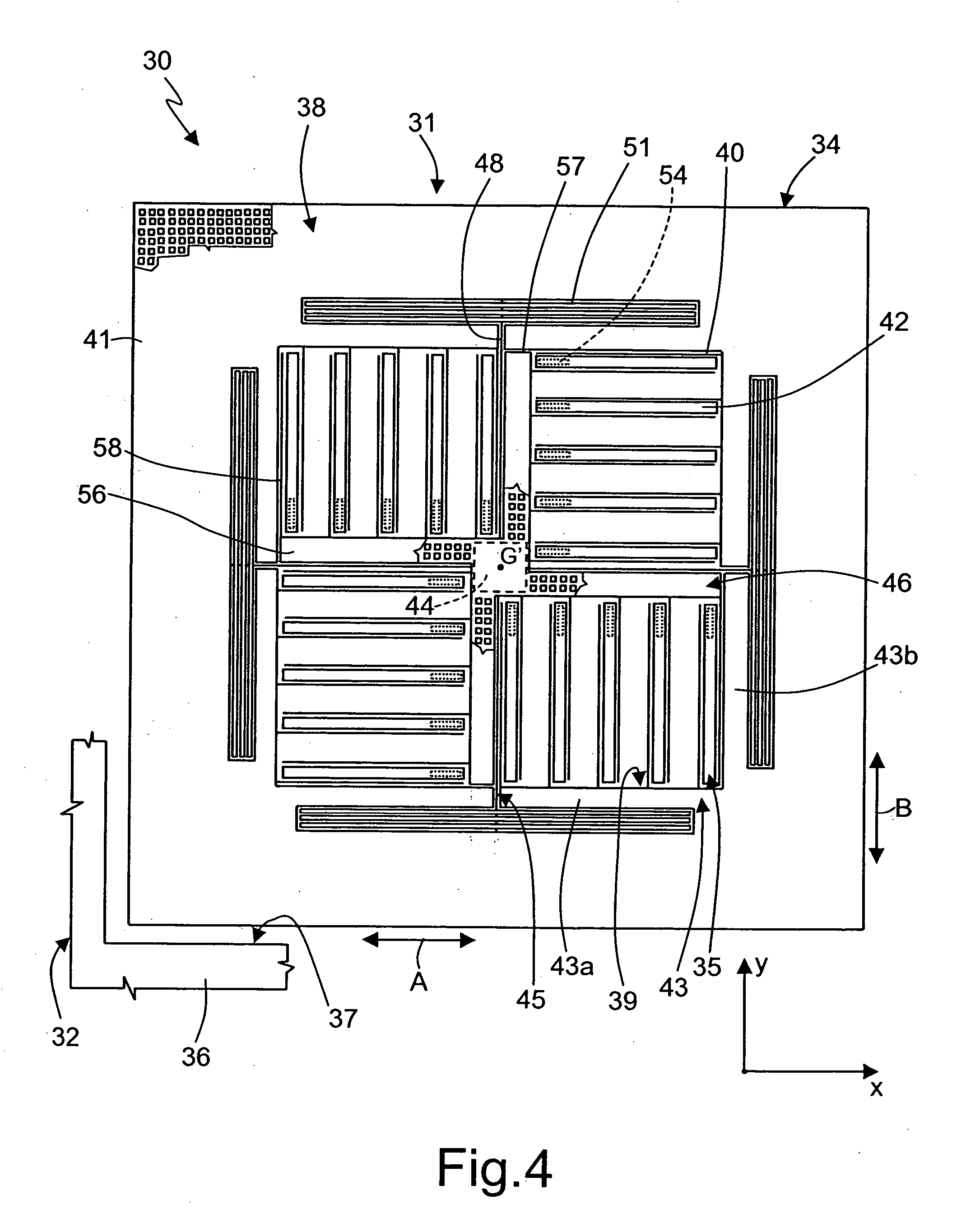
[0037]FIG. 4 shows a biaxial accelerometer 30 of linear type, having a thermal-drifts compensation structure similar to the structure described previously for the uniaxial accelerometer 1.
[0038] The biaxial accelerometer 30, integrated in a chip 32 of semiconductor material, comprises a detection structure 31, formed by a rotor 34 and a stator 35. The biaxial accelerometer 30 has a centroidal axis G′.
[0039] In detail, the rotor 34 comprises a suspended mass 38, which has a peripheral region 41 substantially square frame-shaped, may be surrounded by a fixed structure 36 and may be separated therefrom by a peripheral trench 37.
[0040] The suspended mass 38 may be supported and biased by a suspension structure, comprising a rotor-anchoring element 44 and elastic elements 45.
[0041] The rotor-anchoring element 44 has a substantially square shape, may be centered on the centroidal axis G′, and may be anchored to the substrate (not illustrated) of the chip 32.
[0042] The elastic elements...
second embodiment
[0055] With the second embodiment it is possible to arrange stator anchorages, common to a plurality of fixed electrodes 63, in the proximity of the centroidal axis G′ of the structure and hence in the proximity of the rotor-anchoring portion 44. Thereby, minimization of the relative displacements between the stator and rotor anchorages and thus minimization of the thermal drifts due to the deformation of the chip may be obtained. The smaller the drifts to be compensated, the greater the effectiveness of the self-compensation ensured by the compensation structure according to the present invention.
[0056] With the accelerometers described, it may be possible to integrate the compensation structure within the micro-electromechanical structure, without requiring additional electronic components and without the need for complicated setting and calibration procedures. In practice, a self-compensation in temperature may be obtained that is intrinsic to the micro-electromechanical structur...
PUM
 Abstract
Description
Claims
Application Information