Electrolytic depilation device

a technology of depilation device and electrode, which is applied in the direction of modulated carrier system, transmission, heating surgical instruments, etc., can solve the problems of difficult use, difficult to distribute current equally among all the needles, and the device described there is relatively complicated and difficult to us

Inactive Publication Date: 2007-10-11
TREZON MICHEL
View PDF5 Cites 16 Cited by
  • Summary
  • Abstract
  • Description
  • Claims
  • Application Information

AI Technical Summary

Problems solved by technology

One disadvantage of these depilation devices it that it is difficult to distribute the current equally among all the needles.
One solution to this problem is proposed in U.S. Pat. No. 4,155,363, but the device described there is relatively complicated and difficult to use.
Such a device is described in U.S. Pat. No. 4,784,136, but the double treatment it offers is complex and it is difficult to handle this device effectively and quickly.
However, the use of a stylus is tedious and the patches must be applied carefully relative to one another in order to be effective.

Method used


Image

  • Electrolytic depilation device
  • Electrolytic depilation device
  • Electrolytic depilation device

Examples


first embodiment

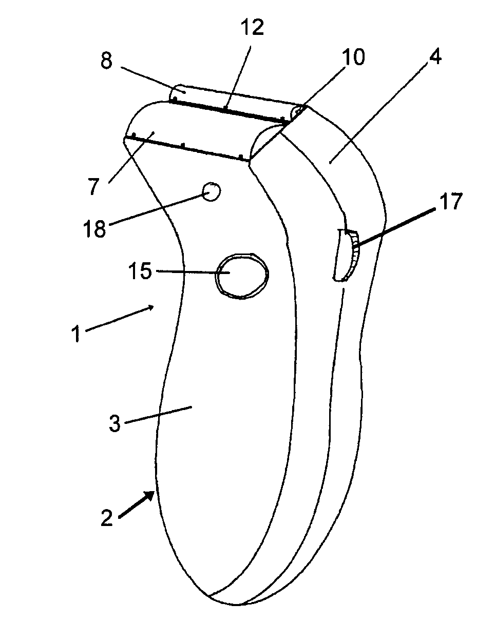
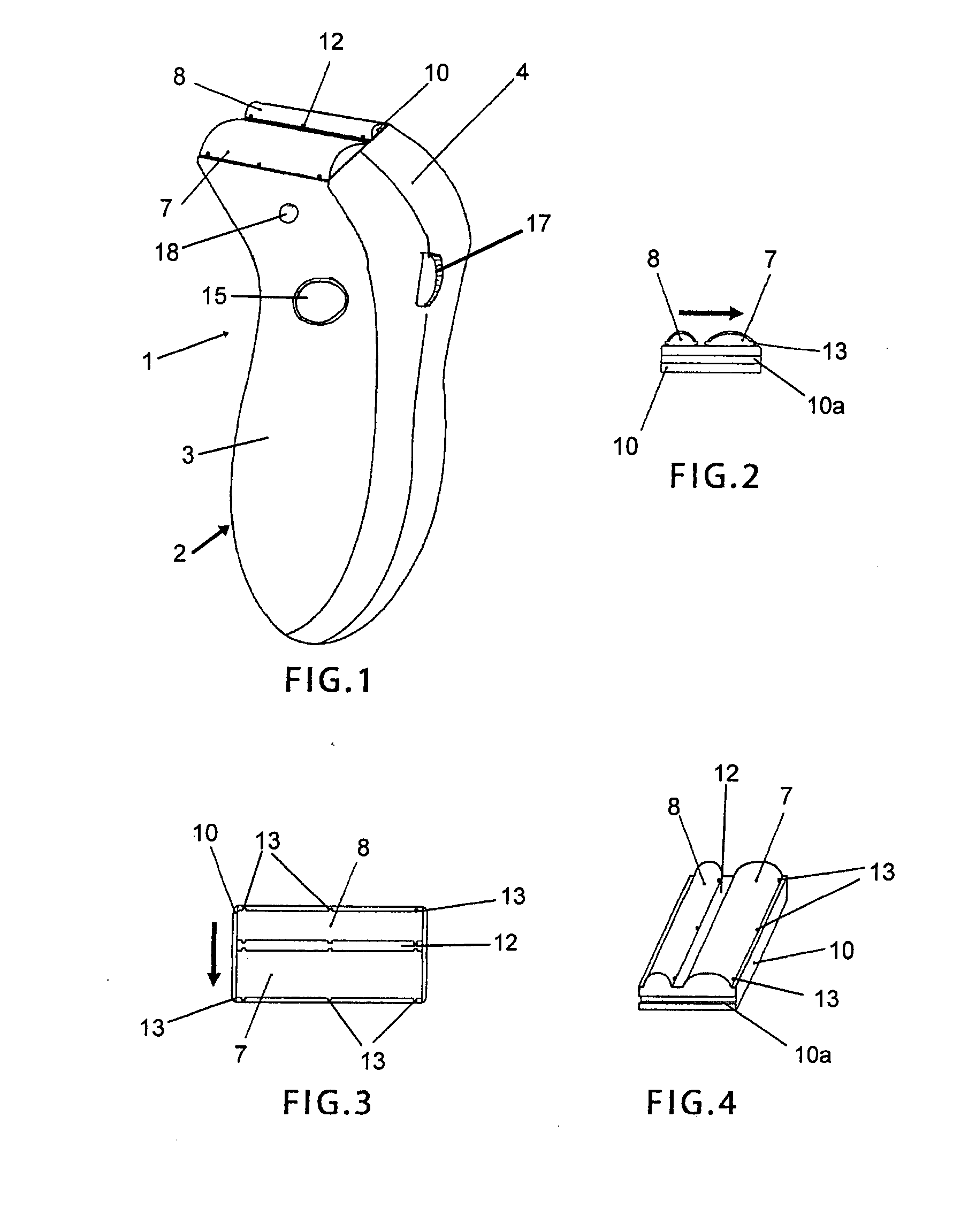
[0036]the electrolytic depilation device 1 according to the invention is shown in FIGS. 1 to 4. This depilation device comprises a case 2 composed of two half-shells 3, 4 connected to one another by connecting means (not shown). In a manner known in the art, the case conventionally contains an electrical power supply source 5 connected to an electronic control circuit 6 (FIGS. 9 and 10).

[0037]The electronic control circuit 6 is thus connected to this electrical power supply source to feed a first electrode 7 and a second electrode 8 of different polarity, located at a distance from one another to apply a current that initiates electrolysis at the level of the hairs to be treated (not shown).

[0038]Preferably the electrical power supply source 5 comprises one or more batteries (not shown) that are integrated into the depilation device 1. The voltage of each battery is preferably 1.2 V and with three batteries in series, 3.6 V are thus obtained. These batteries deliver a continuous cur...

second embodiment

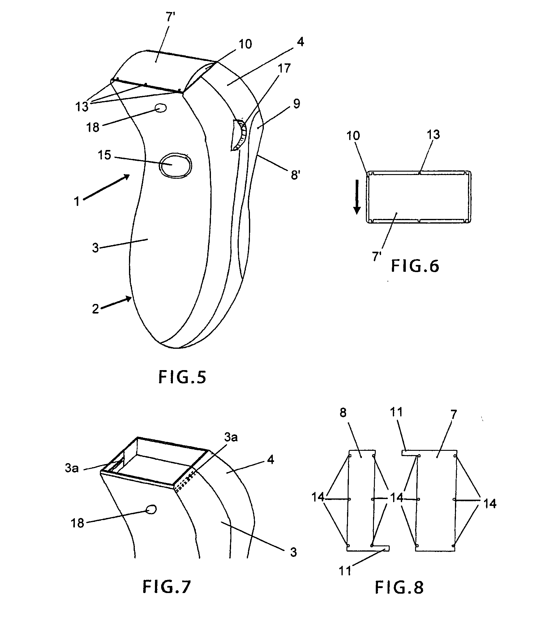
[0052]The first electrode 7′ in the second embodiment shown in FIGS. 5 and 6 is also comprised of such a thin metal sheet.

[0053]The thin metal sheets comprising the electrodes 7, 7′ and 8 are fastened to the support 10 using pins 13 provided on the periphery of the support. These pins 13 are aligned with holes 14 provided in the metal sheets (see FIG. 8).

[0054]Another means of fastening the metal sheets consists in inserting them into the gap that has not yet been filled by the separate spacer element 12, joining the two ends of each sheet by making them overlap one another, and fastening the ends together with screws against the back surface of the support 10.

[0055]The supply of electric current from the power supply source 5 is controlled by a start-stop push button 15 located on the front surface of the depilation device 1.

[0056]The electronic control circuit 6 of the depilation device 1 comprises preferably a processor 16 containing several stored programs allowing differentiate...


PUM


Abstract

The electrolytic depilation device works by electrical contact with the skin of an individual whose hair is to be treated by electrolysis. It comprises a case containing an electrical power supply source, an electronic control circuit connected to the electrical power supply source for supplying a first electrode and a second electrode of different polarity. The electrodes are located at a distance from one another to apply a current that initiates electrolysis at the level of the hairs to be treated. At least the first electrode is elongated and located on one of the ends of the case so as to be applied against the skin over its entire length. The electrode has a shape that is convex in cross section.

Description

TECHNICAL DOMAIN[0001]This invention relates to an electrolytic device for depilation by electrical contact with the skin of an individual whose hair is to be treated by electrolysis.[0002]In depilation devices of this type, a continuous current supplied to the entry of a hair follicle is used to reach the papilla joined to the root of the hair and to consequently chemically destroy the papilla by galvanic electrolysis. The liquid contained in the tissue then constitutes an electrolyte during this procedure. Thanks to this electrolysis the root of the hair is destroyed and its regrowth is greatly delayed.TECHNOLOGICAL BACKGROUND OF THE INVENTION[0003]Electrolytic depilation devices are known in which several needles are used to implement depilation by electrolysis. These needles must be applied to the vicinity of the papillae of the hairs to be treated. The needles comprise first electrodes inserted into the skin of the individual in the vicinity of the respective papilla, whereas a...

Claims


Application Information

Patent Timeline
Patent Type & Authority Applications(United States)
IPC IPC(8): A61B18/14H03G3/30H04B1/04
CPCH03F1/0205H03F1/32H03F3/45085H03F2200/294H04L27/368H03G3/3047H04L27/2017H04L27/361H04L27/362H03F2200/372
Inventor TREZON, MICHEL
Owner TREZON MICHEL
Why Eureka
Try Eureka