Backflow Preventer

a backflow preventer and flue technology, applied in the field of flue backflow preventers, can solve the problems of increasing the size or volume of the device as it is installed, increasing the cost of design, installation, maintenance, and inconvenience, and achieve the effect of reducing the backflow in the pressure zon

Inactive Publication Date: 2007-10-18
A R I FLOW CONTROL ACCESSORIES LTD
View PDF14 Cites 36 Cited by
  • Summary
  • Abstract
  • Description
  • Claims
  • Application Information

AI Technical Summary

Benefits of technology

[0015] According to the present invention there is provided a reduced pressure zone backflow preventer, herein the specification and claims referred to in short as an ‘RPZBP’ wherein the above disadvantages are substantially reduced or overcome and where the above advantages are exploited.

Problems solved by technology

In some prior art backflow preventers the inlet and outlet ports are non-parallel and / or non-coaxial and / or provide flow in opposite directions with respect to one another resulting in the need for additional fittings for installation in a so called ‘in-line’ installation (which is common in point-of-use applications), undesirably adding to the cost of design, installation, maintenance and the like, as well as potentially increasing the size or volume of the device as installed.
Such configurations are believed to be inconvenient in many situations, in particular at point-of-use installations, where the available space for accommodating access to the device is restricted.
Such coupling devices typically add to the volume, length and / or weight of the total assembly, as well as to the general labor and costs involved.
This necessarily leads to relatively high costs of fabrication, assembly, maintenance and repair, and is further not suitable at tight space installations, as mentioned hereinabove.

Method used


Image

  • Backflow Preventer
  • Backflow Preventer
  • Backflow Preventer

Examples


Embodiment Construction

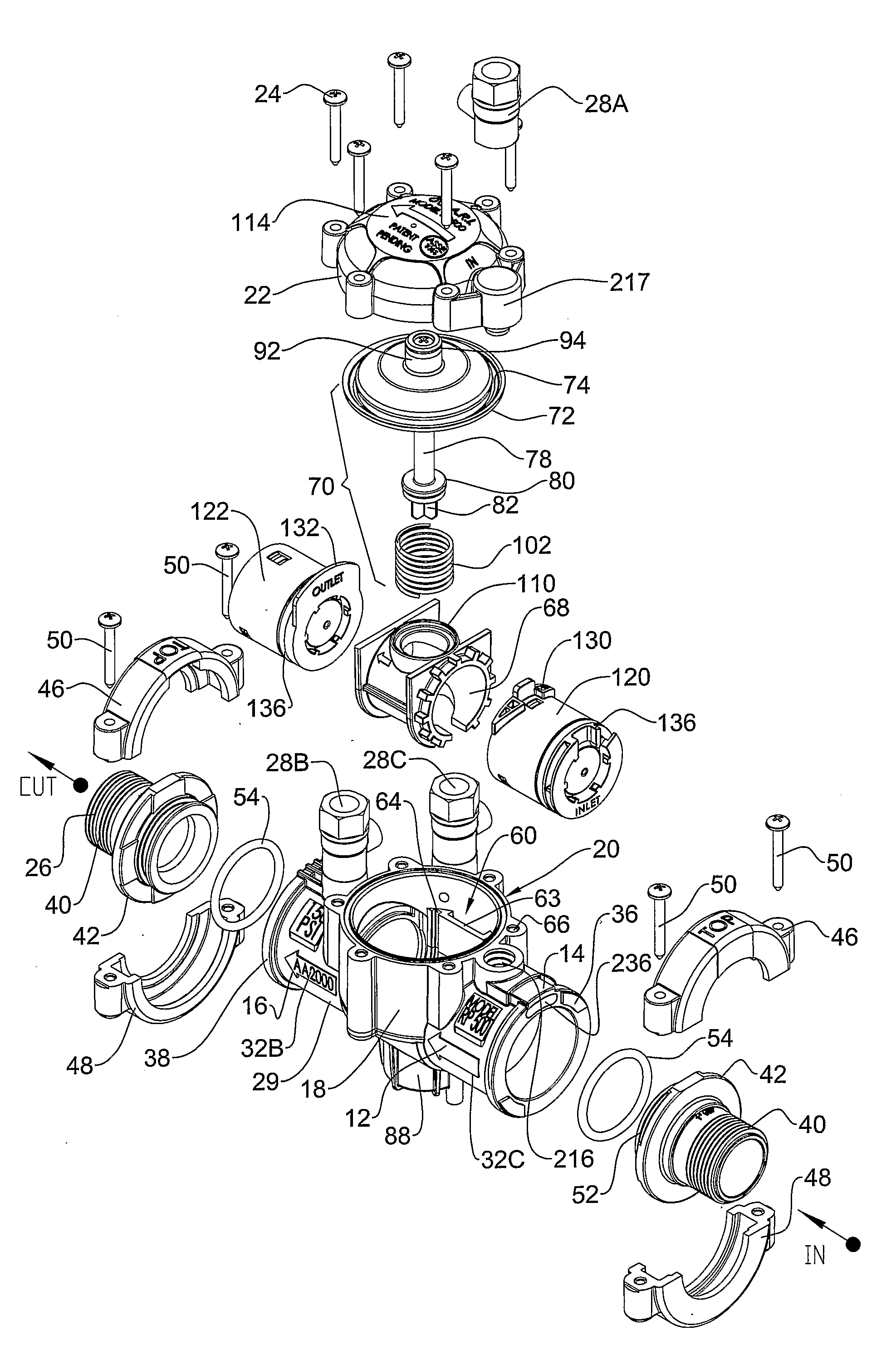
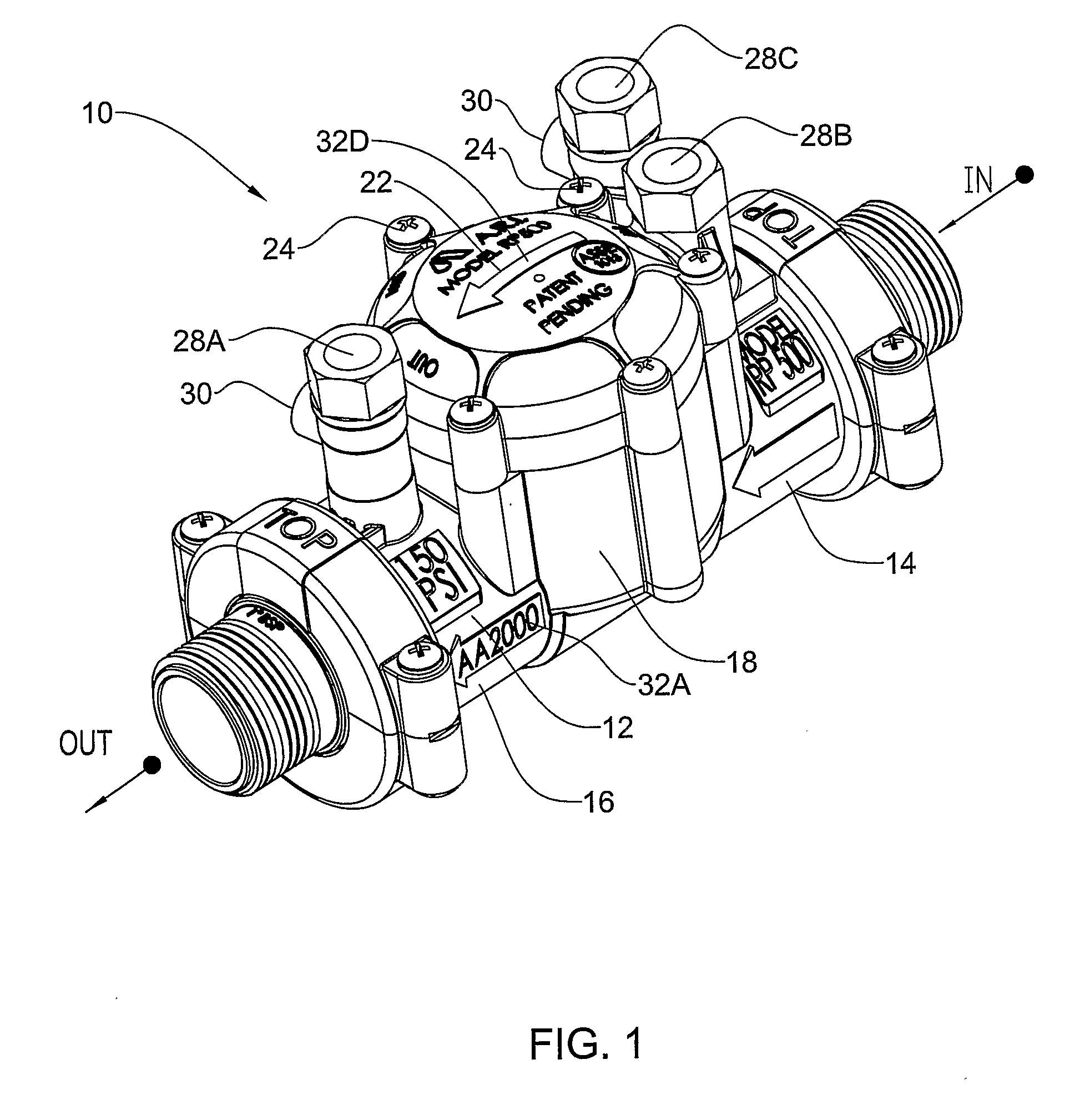
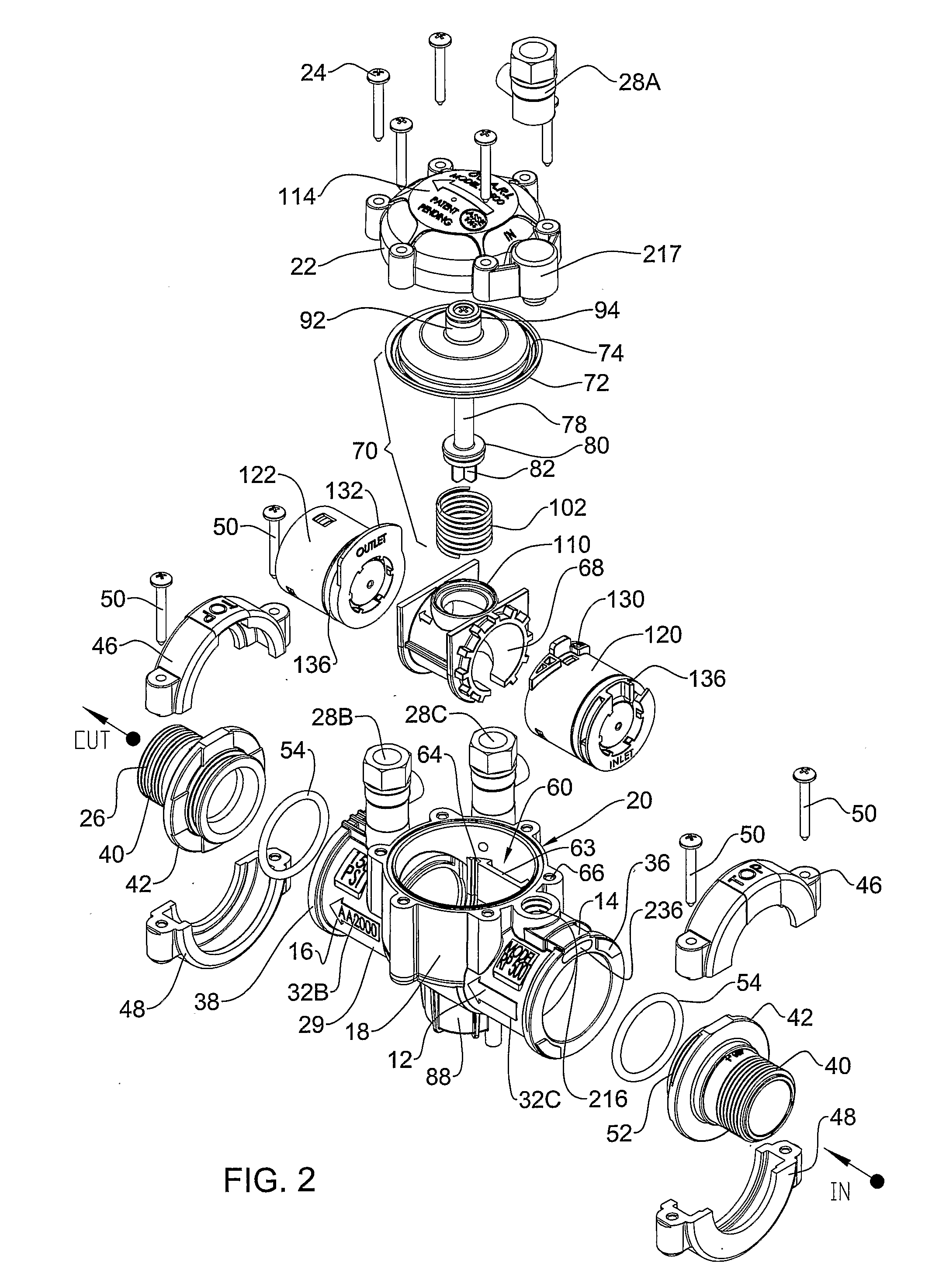
[0054] Attention is first directed to FIG. 1 of the drawings for general familiarization with the backflow preventer device according to the present invention, formed with an elongate cylindric body 12 made of rigid plastic material extending between an inlet end with an inlet port 14 and an outlet end with an outlet port 16, coaxially aligned. The body is a uniform rigid solid structure made of plastic material, optionally of composite material for reinforcement thereof.

[0055] The body 12 further comprises an upright extending cylindrical portion 18 extending at a right angle with respect to the longitudinal axis of the body 12 and formed with an opening (29 in FIG. 2) sealingly covered by a cover 22 fixedly secured in place by a plurality of screws 24.

[0056] Three test cocks 28A (being in flow communication with the inlet port through aperture 59; see FIG. 3A), 28B (being in flow communication with the central space 60 through aperture 61; see FIG. 3A) and 28C (being in flow com...


PUM


Abstract

A reduced pressure zone backflow preventer comprising a body 12 entirely made of plastic material, formed with an inlet port (14) accommodating an inlet check valve assembly 120 and an outlet port accommodating an outlet check valve assembly 122. The check valve assemblies extend along a coaxial axis coinciding with a longitudinal axis of the body. A central space 60 formed between the check valves is accessible through a service opening in the body. A relief valve assembly 70 is received within the central space and a drain port extends from the space. The relief assembly is responsive to pressure differential between the inlet port and the space by a flow passage extending between the inlet port and an upper side of a pressure diaphragm of the relief valve assembly.

Description

FIELD OF THE INVENTION [0001] The present invention relates to fluid backflow preventers and more particularly it is concerned with Reduced Pressure Zone backflow preventers, often referred to as RPZ. Even more specifically, the present invention is concerned with structural features of an RPZ. BACKGROUND OF THE INVENTION [0002] Backflow preventers are well known and are typically used for allowing flow of water (or other fluid) from a source (such as a municipal water supply) to an end user (consumer). A backflow preventer is used to prevent flow of the fluid (e.g. water) in the reverse direction (e.g., for avoiding contamination of a municipal potable water supply, by contaminated water, chemicals, fertilizers, and pesticides and the like which may be supplied through an automatic dosing device, etc.). Such systems are often obligatory under different municipal and other codes and requirements. [0003] A number of configurations are known in the art for avoiding backflow including ...

Claims


Application Information

Patent Timeline
Patent Type & Authority Applications(United States)
IPC IPC(8): E03C1/10F16K15/06
CPCE03B7/077E03C1/108E03C1/106Y10T137/3331
Inventor KATZMAN, YOUVALKANDANYAN, MORDECHAIGRINBERG, JACOBSHUVAL, MEIR
Owner A R I FLOW CONTROL ACCESSORIES LTD
Why Eureka
Try Eureka