Guide plate for side air bag

Inactive Publication Date: 2007-10-18
AUTOLIV DEV AB
View PDF22 Cites 13 Cited by
  • Summary
  • Abstract
  • Description
  • Claims
  • Application Information

AI Technical Summary

Benefits of technology

[0038] Accordingly, the present invention has been made keeping in mind the above problems occurring in the prior art, and an object of the present invention is to provide a guide plate

Problems solved by technology

Meanwhile, if a side collision occurs, a roof side rail portion is severely deformed and is significantly intruded into a passenger space to decrease the size of the passenger space, by which an occupant's head injury rating increases.
In the conventional side air bag, since an inside guide structure is deformed by an external shock, the deployability of the side air bag is degraded.
Also, since separate means for restraining the side air bag from being upwardly deployed is not provided, force is spread and it is difficult to bend the head liner so as to deploy the side air bag.
Further, since a reinforcing part is not formed on either side of the side air bag, it is difficult to sequentially deploy the side air bag.
Moreover, as the side air bag is not properly guided into the inside space, that is, the passenger space of

Method used


Image

  • Guide plate for side air bag
  • Guide plate for side air bag
  • Guide plate for side air bag

Examples


first embodiment

[0084] Hereafter, the construction of a guide plate for a side air bag in accordance with a first embodiment of the present invention will be described with reference to FIGS. 4 through 6.

[0085] Referring to FIG. 4, a side air bag 10a is installed inside a roof side panel 20a. The side air bag 10a has a front end which is secured to a front pillar 50a by a buckle and a rear end which has an inflator 40a and is connected to a rear pillar 70a.

[0086] A guide plate 100 according to the present invention is installed on the roof side panel 20a above a center pillar 60a. A side air bag housing 10b is fitted between a retaining member 120 and a support member 130 of the guide plate 100.

[0087] While not shown in the drawings, the side air bag 10a includes a sensor for sensing a collision of a vehicle and an electronic control unit for operating the inflator 40a in response to a signal from the sensor.

[0088]FIGS. 5 and 6 illustrate in detail the guide plate for a side air bag according t...

second embodiment

[0105] FIGS. 7(a) through 7(c) illustrate constructions of the guide plate in accordance with a second embodiment of the present invention.

[0106] Referring to FIG. 7(a), the retaining member 120, which projects from the surface of the fastening member 110, has extended retaining members 121 which are respectively and integrally formed on both lengthwise ends of the retaining member 120, to prevent force from being spread in the upward direction.

[0107] Referring to FIG. 7(b), the support member 130 has the extended members 131 which are respectively and integrally formed on both lengthwise ends of the support member 130, to prevent the side air bag 10a from interfering with the center pillar 60a when being deployed.

[0108] Referring to FIG. 7(c), an engagement member 122 is formed on the distal end of the retaining member 120 to be bent in the downward direction. The engagement member 122 securely holds the side air bag housing 10b and causes the side air bag tube 10c to be reliabl...

third embodiment

[0110] A guide plate for a side air bag in accordance with a third embodiment of the present invention will be described below with reference to FIGS. 9 through 12.

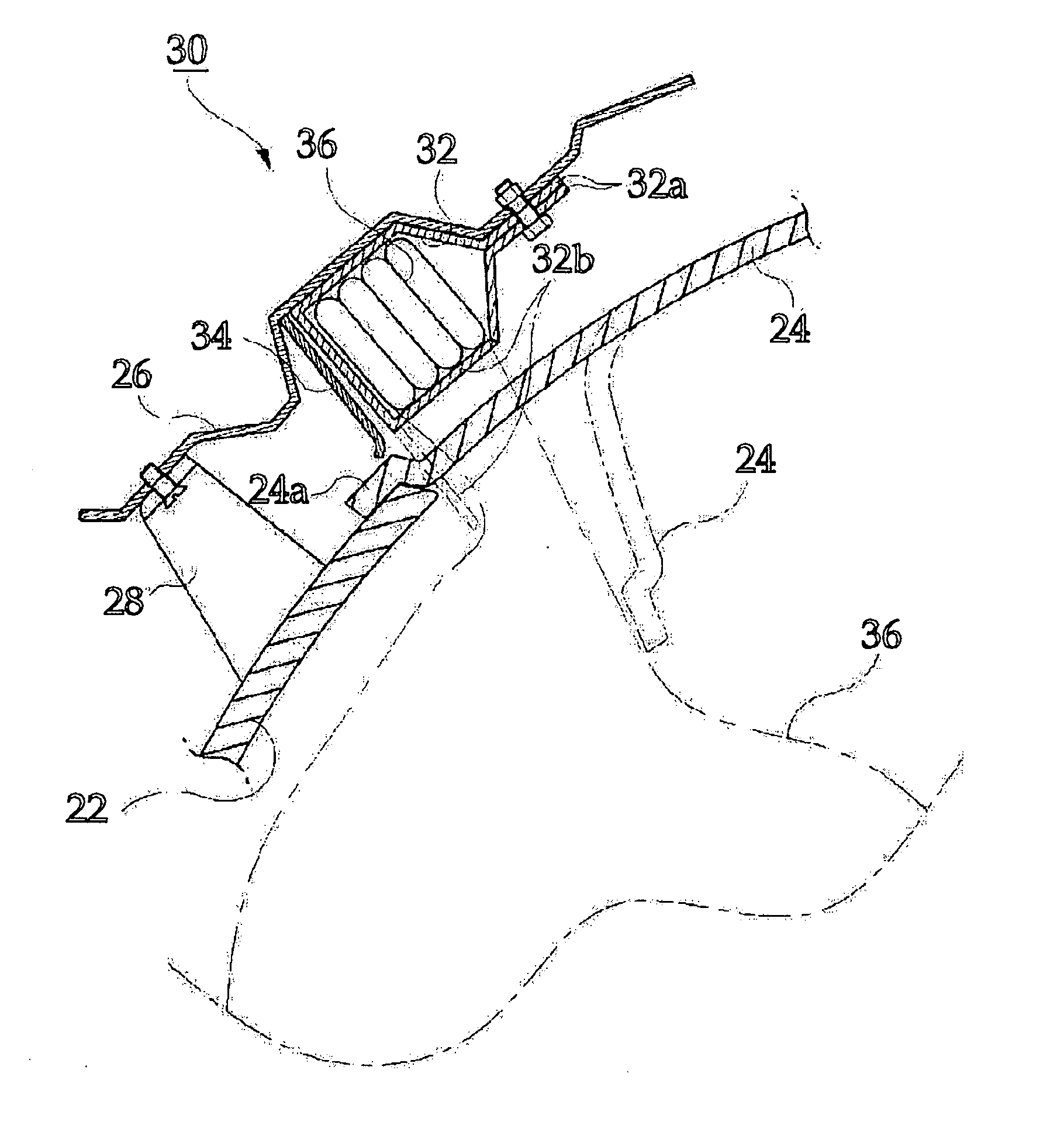
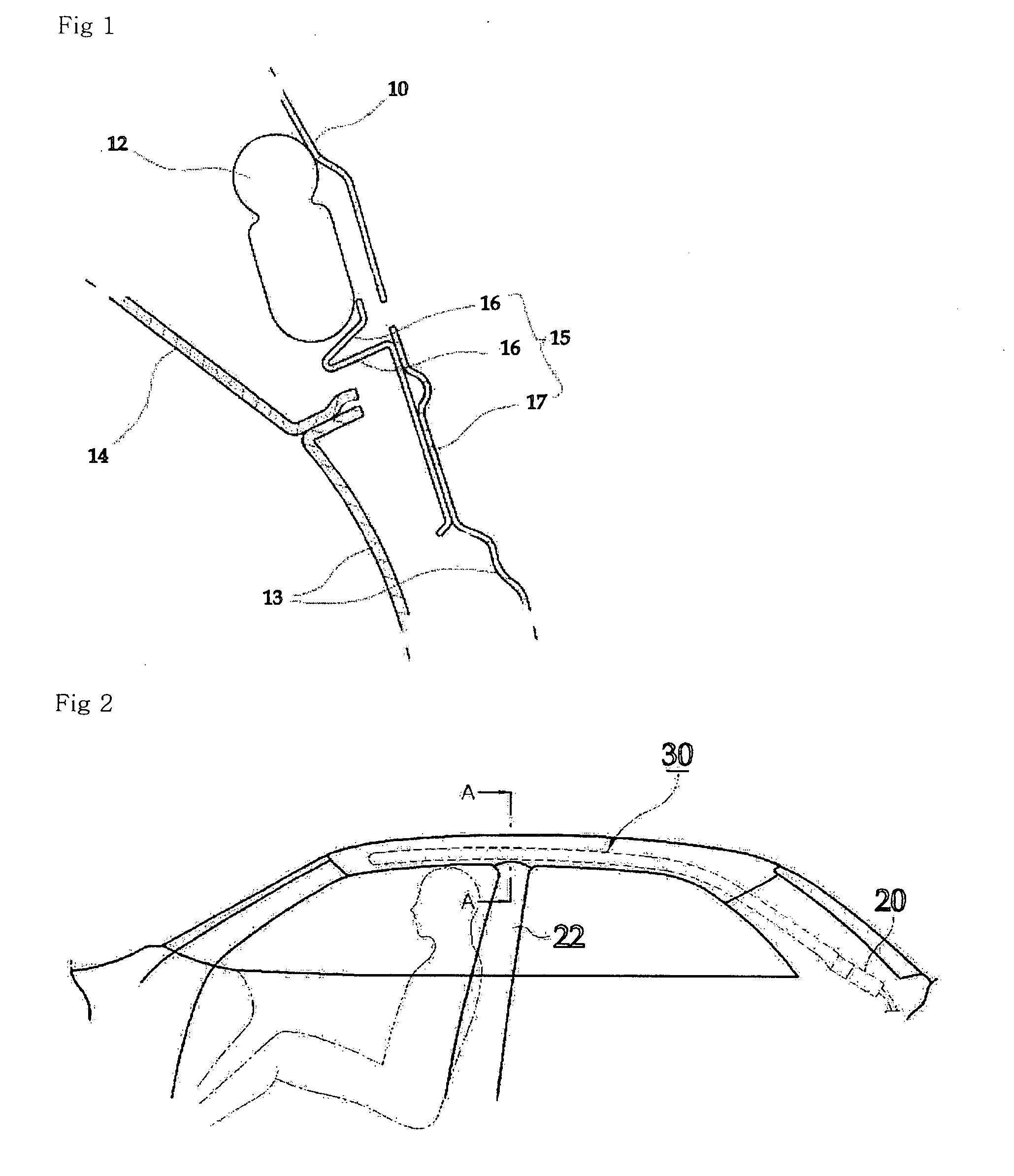
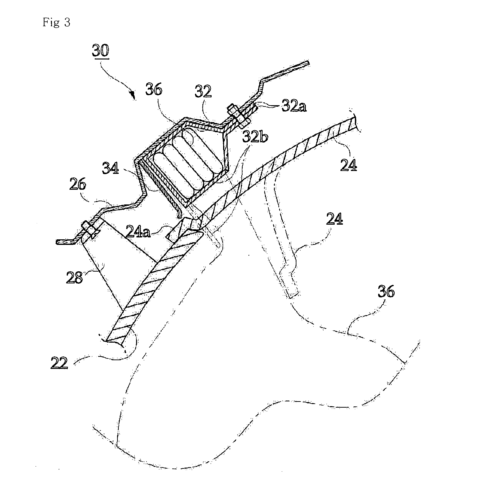
[0111] Referring to FIG. 11, a side air bag 30 is installed facing the passenger space of a vehicle to protect an occupant from being injured. The side air bag 30 includes an air bag tube 36 which is folded multitude of times, an air bag housing 32 for receiving the air bag tube 36, and an inflator connected to an end of the air bag tube 36 to inject gas under a high pressure into the air bag tube 36.

[0112] The air bag housing 32 has a door 32b on one sidewall thereof and a mounting portion (not shown) on the upper end thereof, which is to be fastened to an inner panel 26 by a bolt. Each guide plate 200 is installed on the air bag housing 32 at a predetermined position to support the lower surface of the air bag housing 32 (see FIG. 12).

[0113] Referring to FIGS. 9 and 12, the guide plate 200 for a side air bag 30 to su...


PUM


Abstract

There is provided a guide plate for a side air bag. The guide plate includes a fastening member fastened to an inner surface of a vehicle body, a support member bent from a lower end of the fastening member and extending toward a passenger space of a vehicle, and a retaining member extending from a surface of the fastening member toward the passenger space of the vehicle. As the guide plate prevents a side air bag tube from being deployed in an upward direction, force for deploying the side air bag tube is not spread but concentrated to allow the side air bag tube to be properly deployed by opening a head liner.

Description

CROSS-REFERENCE TO RELATED APPLICATION [0001] This application claims the benefit of Korean Utility Model Application No. 2006-0008880 filed on Apr. 4, 2006, No. 2006-0010396 filed on Apr. 18, 2006 and No. 2006-0010487 filed on Apr. 19, 2006, the disclosure of which is hereby incorporated herein by reference in its entirety. BACKGROUND OF THE INVENTION [0002] 1. Technical Field [0003] The present invention relates to a guide plate for a side air bag, and, more particularly, to a guide plate for a side air bag, which prevents a side air bag from being upwardly deployed so as to allow it to be easily deployed in a downward direction, and ensures sequential deployment of a side air bag tube when the side air bag is deployed. [0004] 2. Discussion of Related Art [0005] As is generally known in the art, in an air bag for an automotive vehicle, a sensor is provided to sense impact force upon occurrence of a collision or a sudden stop during high speed running. Therefore, as a signal is tra...

Claims


Application Information

Patent Timeline
IPC IPC(8): B60R21/213B60R21/215B60R21/20B60R21/261
CPCB60R21/213B60R21/232B60R2021/161H04W84/04H04W60/00H04W76/027H04W28/04H04W76/18
Inventor JANG, MYUNG-RYUNYOO, BYOUNG-SUNKIM, TAE-WOOLEE, DONG-JUNOH, EUN-HWANCHOI, KYUN-SOON
Owner AUTOLIV DEV AB
Why Eureka
Try Eureka