Plug/unplug moudle base

a module base and plug-in technology, applied in the direction of coupling device connection, coupling device two-part connection, coupling/disengagement of coupling parts, etc., can solve the problems of easy elastic component exhaustion or damage, complicated manufacturing procedure, and high cost, and achieve simple and easy manufacturing process of elastic components

Inactive Publication Date: 2007-10-18
ALL BEST ELECTRONICS
View PDF2 Cites 57 Cited by
  • Summary
  • Abstract
  • Description
  • Claims
  • Application Information

AI Technical Summary

Benefits of technology

[0005] In view of the shortcoming of the traditional plug / unplug module base, the inventor of the present invention based on years of experience in the related industry to conduct extensive researches and experiments, and finally invented a plug / unplug module base in hope of making the manufacturing process of the elastic component simple and easy and providing a durable and powerful elastic component.
[0006] Therefore, it is a primary objective of the present invention to provide a plug / unplug module base capable of installing its elastic components independently, making the manufacturing process of the elastic component simple and easy, and providing a durable and powerful elastic component to overcome the prior art.
[0007] To achieve the foregoing objective, the present invention provides a plug / unplug module base comprising: at least one plug / unplug channel and a plug / unplug opening interconnected to the plug / unplug channel; a base disposed at an end of the plug / unplug channel without the plug / unplug opening and having at least one plug / unplug groove, such that when a plug / unplug module enters into the plug / unplug channel, the plug / unplug groove can accommodate a portion or the whole of an plug / unplug terminal of the plug / unplug module; at least one elastic component installed at the base, and when the elastic component at the plug / unplug terminal is contained in the plug / unplug groove, the elastic component is in contact with the plug / unplug module and stores a resilience. Thus, such arrangement makes the manufacturing of the elastic component simple and easy and provides a durable and powerful elastic component.

Problems solved by technology

As a result, the elastic component will become elastically exhausted or damaged easily.
Further, the small elastic component 131 installed on the guiding plate 13 not only makes the manufacturing procedure more complicated, but also incurs a higher cost.

Method used


Image

  • Plug/unplug moudle base
  • Plug/unplug moudle base
  • Plug/unplug moudle base

Examples


Embodiment Construction

[0019] To make it easier for our examiner to understand the objective, features, and performance of the present invention, we use a preferred embodiment together with the attached drawings for the detailed description of the invention.

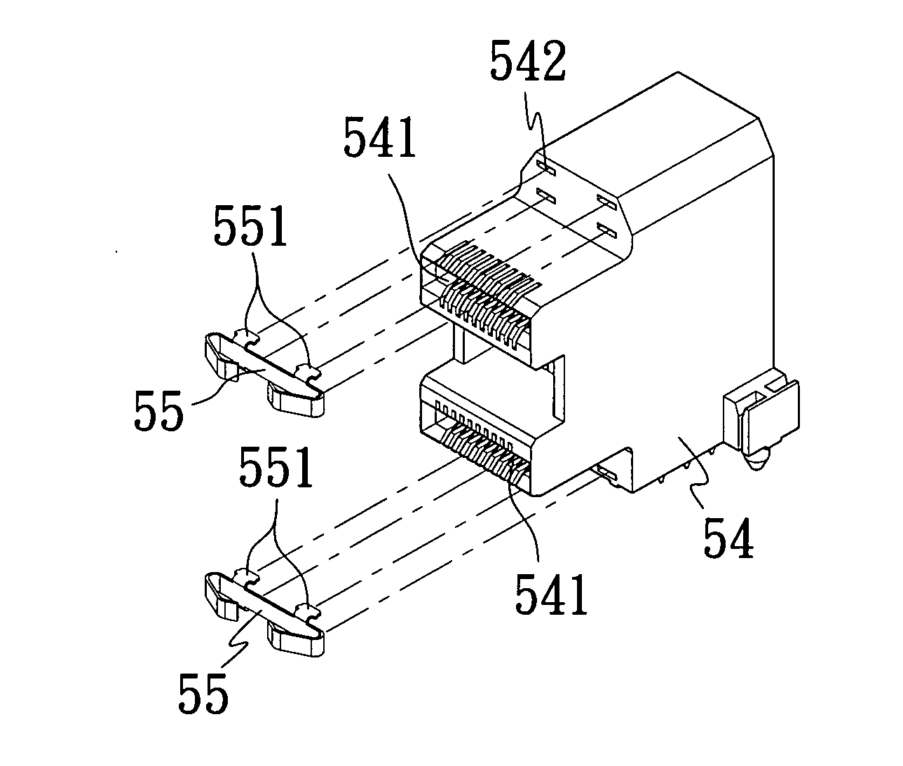
[0020] Referring to FIGS. 5 to 8 for the exploded view and the perspective view of a plastic core and an elastic component, and the exploded view and the perspective view of a preferred embodiment of the invention respectively, a plug / unplug module base of the invention comprises: an upper casing 51, two guiding plates 53, a lower chassis plate 52, a base 54 and two elastic components 55, wherein the base 54 could be a plastic core. The upper casing 51 is a rectangular solid having an opening 511, and an end of the guiding plate 53 has a latch hole 531, and the plastic core 54 has two plug / unplug grooves 541 and eight fixing grooves 542, and the elastic component 55 has four fixing buttons 551. The plug / unplug module base 5 is installed in the upper c...


PUM


Abstract

The present invention discloses a plug / unplug module base capable of installing its elastic components independently. The plug / unplug module base of the invention comes with independent elastic components and features a more powerful, durable and elastic design of the elastic components, and the manufacturing process of the elastic components can be simplified to lower its cost.

Description

FIELD OF THE INVENTION [0001] The present invention relates to a plug / unplug module base, and more particularly to a plug / unplug module base capable of installing its elastic components independently. BACKGROUND OF THE INVENTION [0002] Since present industries rely on the use of a large quantity of electronic devices, and most electronic devices are connected by plug / unplug devices. Referring to FIGS. 1 to 4 for the exploded view, the perspective view, the side view and the schematic view of a traditional plug / unplug module base according to the present invention respectively, the traditional plug / unplug module base comprises: an upper casing 11, two guiding plates 13, a lower chassis plate 12 and a plastic core 14. The upper casing 11 is a rectangular solid having an opening 111, and the guiding plate 13 includes an elastic component 131 at an end of the guiding plate 13 and a latch hole 132 at the other end of the guiding plate 13, and the plastic core 14 includes two plug / unplug ...

Claims


Application Information

Patent Timeline
Patent Type & Authority Applications(United States)
IPC IPC(8): H01R13/62
CPCH01R13/4364H01R24/64H01R13/65802H01R13/4532H01R13/635
Inventor YANG, HAVEN
Owner ALL BEST ELECTRONICS
Why Eureka
Try Eureka