Outboard motor

Inactive Publication Date: 2007-10-18
YAMAHA MOTOR CO LTD
View PDF23 Cites 9 Cited by
  • Summary
  • Abstract
  • Description
  • Claims
  • Application Information

AI Technical Summary

Problems solved by technology

Also, unless the electric component is removed, the surge tank or the intake manifol

Method used


Image

  • Outboard motor
  • Outboard motor
  • Outboard motor

Examples


Embodiment Construction

[0021]The embodiments disclosed herein are described in the context of a small watercraft powered by an outboard motor because the embodiments disclosed herein have particular utility in this context. However, the embodiments and inventions herein can also be applied to other boats having other types of propulsion units as well as other types of vehicles.

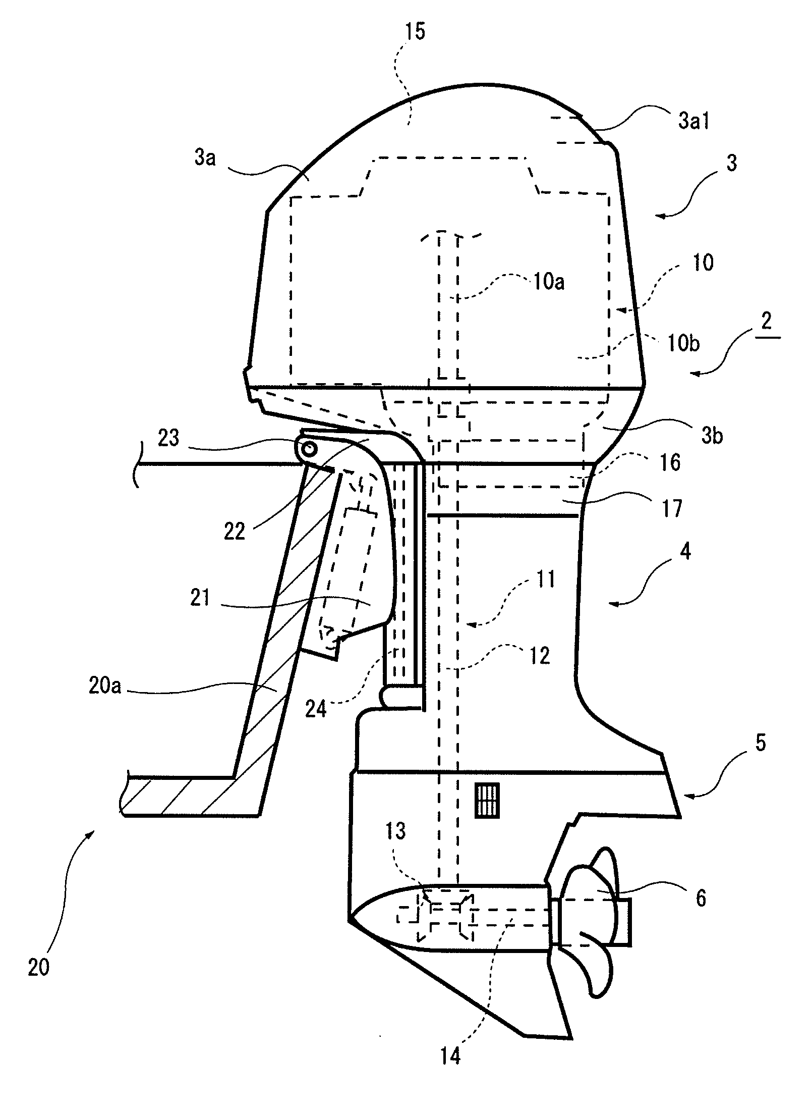
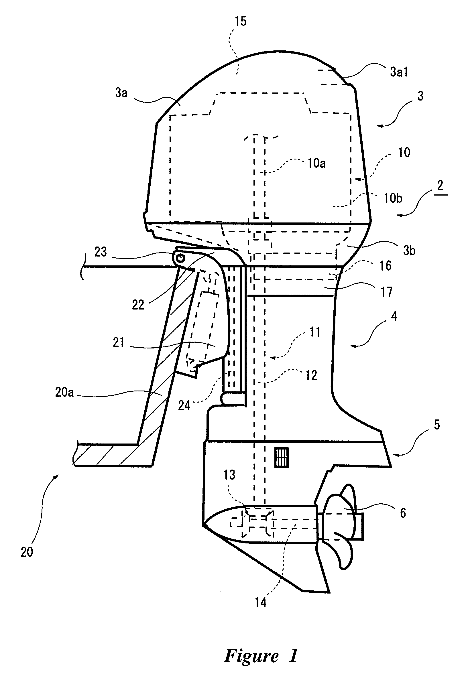
[0022]In the following description, the front side of the outboard motor 1 is defined as hull side, the rear side of the outboard motor 1 indicates the side opposite the hull side, and a direction perpendicular to a horizontal direction is defined as vertical direction.

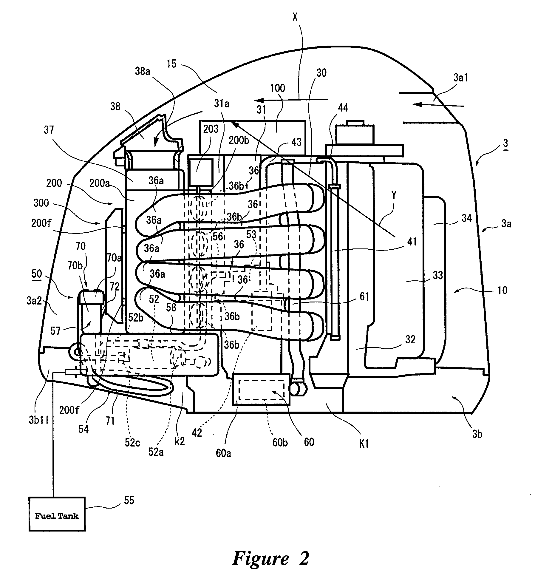
[0023]As shown in FIG. 1, an outboard motor 1 can have a propulsion unit 2 having a housing portion consisting of a cowling 3, an upper case 4 and a lower case 5. An engine 10 can be housed in the cowling 3 on the upper side with its crankshaft 10a extending vertically, and a propeller 6 which can be rotatably driven by the engine 10, can be attached to the lower case...


PUM


Abstract

An outboard motor can be mounted on a transom plate of a hull, and can have an engine disposed in an upright position in a cowling so that a crankshaft thereof extends generally vertically during cruising. A surge tank can be located on the hull side of the engine in the cowling, and a mounting portion for an electric component can be provided on a front face of the surge tank.

Description

PRIORITY INFORMATION[0001]This application is based on and claims priority to Japanese Patent Application No. 2005-114817, filed Apr. 18, 2006, the entire contents of which is hereby expressly incorporated by reference.BACKGROUND OF THE INVENTIONS[0002]1. Field of the Inventions[0003]The present inventions relate to outboard motors, and more particularly, to outboard motors which have an engine disposed in an upright position so that the crankshaft thereof extends generally vertically during cruising.[0004]2. Description of the Related Art[0005]Outboard motors have long been known in the marine propulsion arts. One commonly used design is one in which the crankshaft of the engine in the outboard motor extends generally vertically.[0006]In more recent designs, a surge tank can be provided in an intake passage of the engine located in front of the engine (the propeller side is defined as the rear side). Additionally, an electric component such as an engine control unit (ECU) can be mo...

Claims


Application Information

Patent Timeline
IPC IPC(8): B63H20/32
CPCF02B61/045
Inventor OSAKABE, TAKAYUKIIWATA, YOSHIBUMI
Owner YAMAHA MOTOR CO LTD
Why Eureka
Try Eureka