Liquid nitrogen pump power end assembly

A power end and liquid nitrogen pump technology, which is applied to liquid fuel engines, pumps, pump components, etc., can solve the problems of being unable to connect with foreign liquid power ends and supporting connections, and achieves easy processing and manufacturing, prolonging service life, and simple and compact structure Effect

Pending Publication Date: 2018-09-18
YANTAI JEREH PETROLEUM EQUIP & TECH CO LTD
View PDF7 Cites 103 Cited by
  • Summary
  • Abstract
  • Description
  • Claims
  • Application Information

AI Technical Summary

Problems solved by technology

[0004] The purpose of the present invention is to overcome the problems of the strength of the power end shell of the existing liquid nitrogen pump, the lubrication and heat dissipation of the moving parts, and the problem that it cannot be connected with the liquid power end

Method used


Image

  • Liquid nitrogen pump power end assembly
  • Liquid nitrogen pump power end assembly
  • Liquid nitrogen pump power end assembly

Examples


Embodiment Construction

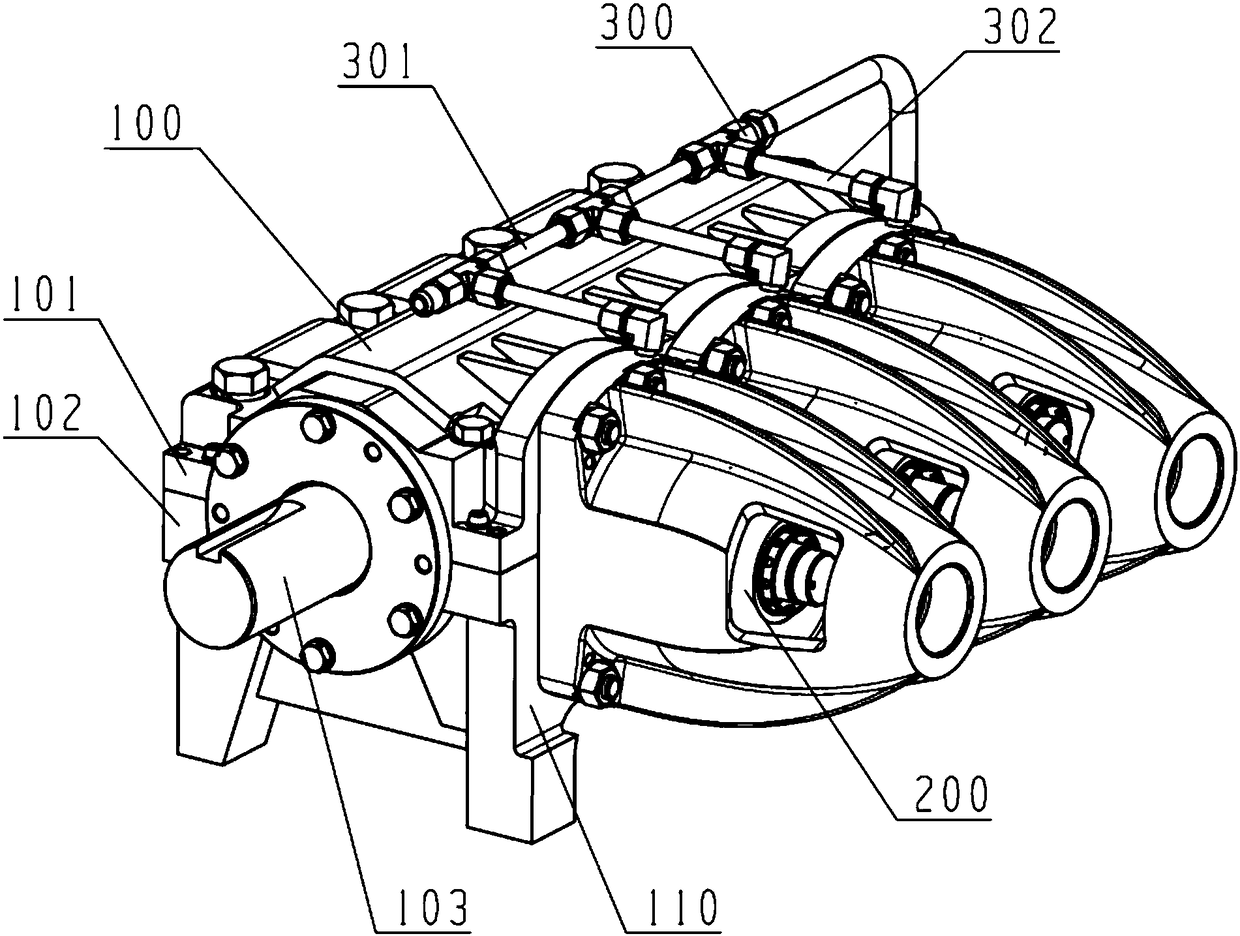
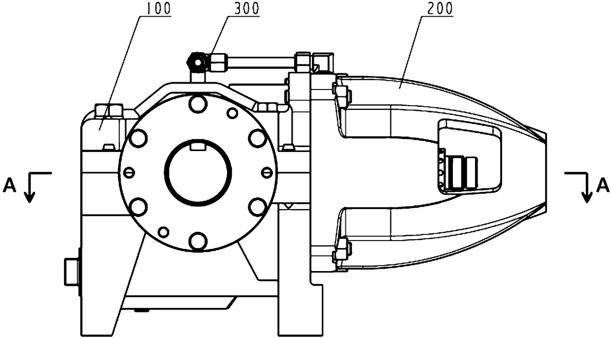
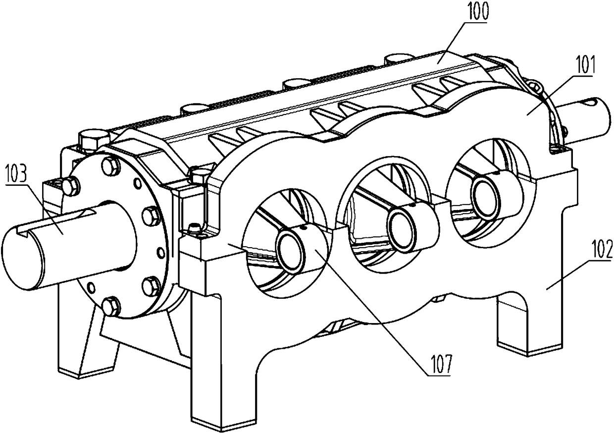
[0028] Examples such as Figures 1 to 6 As shown, a liquid nitrogen pump power end assembly includes a crankcase assembly 100, the crankcase assembly 100 is connected with a cross housing assembly 200 correspondingly, the crankcase assembly 100 and the cross housing assembly 200 A lubrication system 300 is correspondingly provided between them, and the crankcase body assembly 100 includes a crankcase welding shell 110. There are four crankcase bearing seats 109 inside the crankcase welding shell 110, and four crankcase bearing seats 109 are installed correspondingly. Crankshaft bearing 106, crankshaft bearing 106 is provided with crankshaft, crankshaft is connected with connecting rod 107, and crankcase welding shell 110 comprises crankcase casing 101 and crankcase cover 102, and crankcase casing 101 and crankcase cover 102 pass through Eight crankcase fixing bolts 108 are connected, the mating surface of the crankcase body 101 and the crosshead housing assembly 200 is provide...


PUM


Abstract

The invention provides a liquid nitrogen pump power end assembly. The liquid nitrogen pump power end assembly comprises a crankshaft box assembly. The crankshaft box assembly is correspondingly connected with crosshead shell assemblies. Lubricating systems are correspondingly arranged between the crankshaft box assembly and the crosshead shell assemblies. The liquid nitrogen pump power end assembly adopts split type module combination of the crankshaft box assembly and the crosshead shell assemblies to be assembled, a crankshaft box is designed into a welding type, crosshead shells are designed into a casting type, compared with inblock casting or overall welding, the structure is simple and compact, existing machining manners are considered, machining, manufacturing, assembling, repairingand maintaining are facilitated, crossheads are provided with threads for connection and can be connected with fluid ends with different specifications on the market to play a role in transmitting power, a crankshaft adopts a split type structure that a straight shaft and multiple eccentric wheels are connected through flat keys, the crankshaft overall machining difficulty is lowered, crosshead hinge pins are provided with jackscrew holes, by means of jackscrew fixing, axial floating of hinge pins can be eliminated, the lubricating system can protect movement members, and the service life ofeach movement member is prolonged.

Description

technical field [0001] The invention relates to the technical field of liquid nitrogen pumps, in particular to a liquid nitrogen pump power end assembly. Background technique [0002] At present, conventional liquid nitrogen pumps are mainly used to pressurize liquid nitrogen, and the working pressure is generally below 16.5MPa. Its working process is similar to that of ordinary reciprocating pumps. Driven by external power, the rotary motion of the crankshaft is converted into the reciprocating linear motion of the connecting rod, crosshead and plunger, so as to realize the low-pressure suction and high-pressure discharge of the fluid medium. Due to the low pressure of conventional liquid nitrogen pumps, the scope of use is limited. With the change of domestic oilfield operation technology, the pressure gradually increases to 40-100MPa, and the crankshaft speed increases to 600-900rpm. Due to the increase of pressure and speed, the force on the transmission mechanism of th...

Claims


Application Information

Patent Timeline
IPC IPC(8): F04B53/18F04B53/22F04B53/16F04B53/00F04B15/08
CPCF04B15/08F04B53/00F04B53/16F04B53/18F04B53/22F04B2015/0824
Inventor 李朋魏小淞崔海萍王坤
Owner YANTAI JEREH PETROLEUM EQUIP & TECH CO LTD
Why Eureka
Try Eureka