Apparatus for generating electrical power from solar radiation concentrated by a concave reflector

a solar radiation and reflector technology, applied in the direction of light radiation electric generators, thermal-pv hybrid energy generation, lighting and heating apparatus, etc., can solve the problems of limited photovoltaic cells worldwide availability and natural limitation of solar panels, and achieve the effect of higher light and hea

Inactive Publication Date: 2007-10-25
HYDROGAIN TECH +1
View PDF12 Cites 54 Cited by
  • Summary
  • Abstract
  • Description
  • Claims
  • Application Information

AI Technical Summary

Benefits of technology

[0008] Since such arrangements of reflectors reflect sunlight from a relatively large area to a small area around a focal point, the levels of light and heat are higher than those required for efficient operation of photovoltaic devices over long periods of time. Thus, another arrangement, such as a circulating fluid carrying heat away from the heated area and providing for its use through a remote heat exchanger, or heating a surface of a boiler producing steam to drive an engine, is required. Thus, what is needed is an apparatus using a reflector to direct sunlight to an array of photovoltaic cells arranged with the reflector, with the area of the cells being substantially larger than the area in the vicinity of the focal point that is heated by such reflector systems of the prior art. Additionally, it is desirable to incorporate the array within the reflector, so that it is not necessary to provide a structure extending outward from the reflector to a focal point.

Problems solved by technology

The electrical output of such a solar panel is naturally limited by the efficiency of the photovoltaic cells and by the total area of the photovoltaic cells exposed to the ambient level of solar radiation.
It is particularly desirable to substantially increase the electrical output of a number of solar cells above the level that can be provided with the cells merely exposed to ambient sunlight, particularly since the cost of the photovoltaic cells represents a significant portion of the total cost of providing electrical power from solar energy, and additionally because the worldwide availability of photovoltaic cells is limited.

Method used


Image

  • Apparatus for generating electrical power from solar radiation concentrated by a concave reflector
  • Apparatus for generating electrical power from solar radiation concentrated by a concave reflector
  • Apparatus for generating electrical power from solar radiation concentrated by a concave reflector

Examples


first embodiment

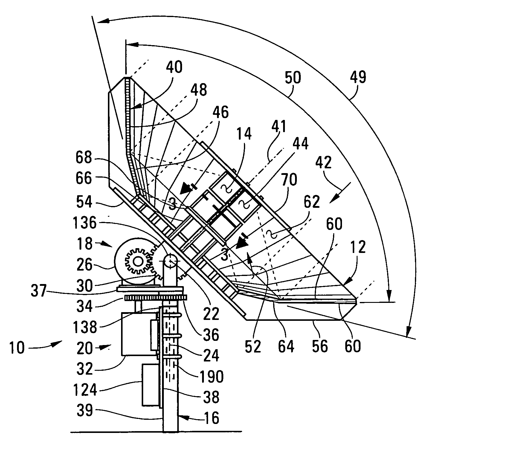
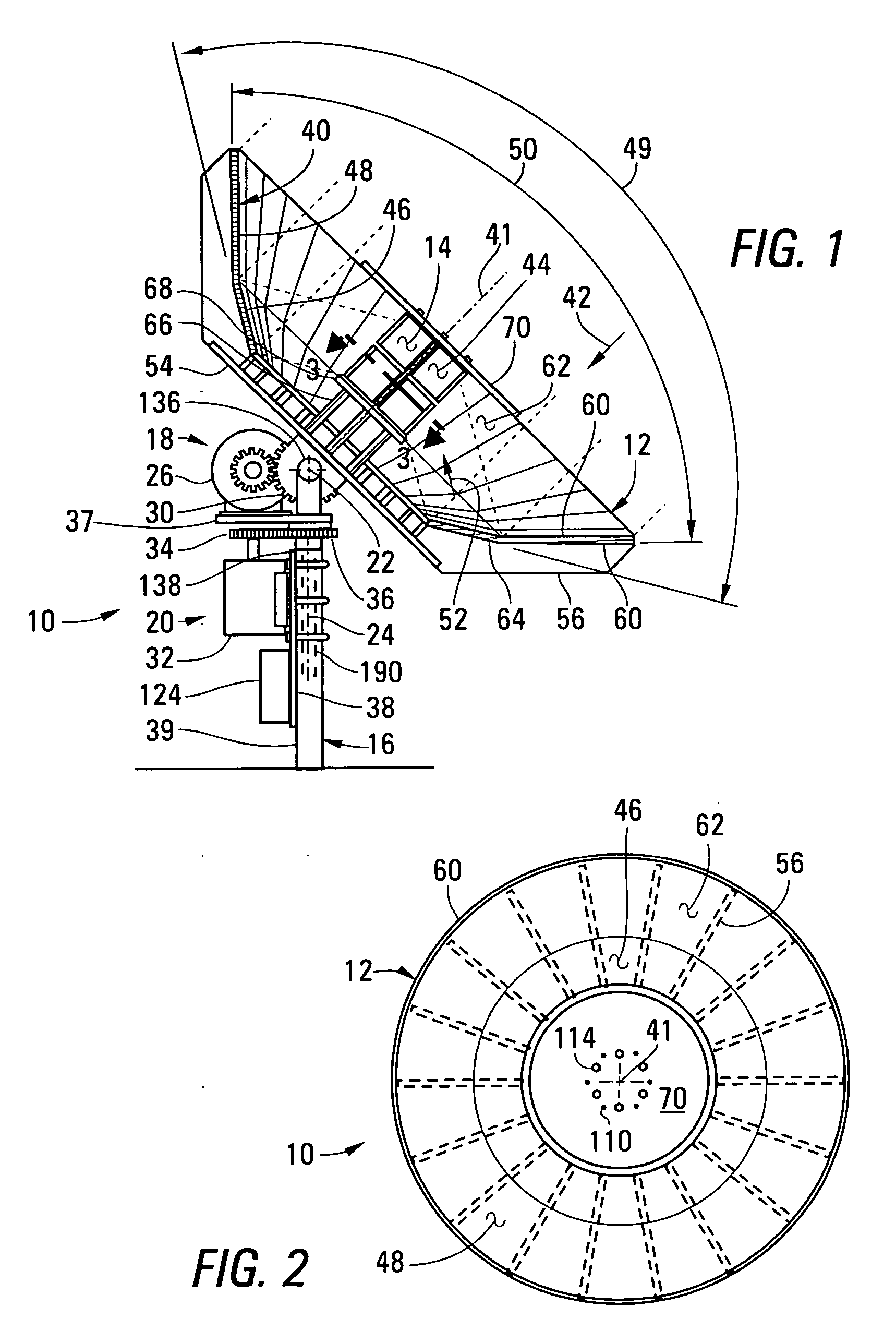
[0024]FIG. 1 is a vertical cross-sectional elevation of an electrical power generator 10 built in accordance with the invention. The electrical power generator 10 includes a concave reflector 12, an energy receiving structure 14, a stationary mounting structure 16, a first pivotal mounting structure 18, and a second pivotal mounting structure 20. The pivotal mounting structures 18, 20 together attach the concave reflector 12 to the stationary mounting structure while providing an ability for the concave reflector to pivot about a first axis of rotation 22 and a second axis of rotation 24, perpendicular to the first axis of rotation 22. A first motor 26 is provided for pivoting the concave reflector 12 about the first axis of rotation 22 by rotating a drive gear 28 engaging a sector gear 30 attached to the concave reflector 12. A second motor 32 is provided for pivoting the concave reflector 12 about the second axis of rotation 24 by rotating a drive gear 34 engaging a sector gear 36...

second embodiment

[0040]FIG. 10 is a vertical cross-sectional elevation of an alternative electrical power generator 200 built in accordance with the invention to include a first pivotal mounting structure 202 to provide for pivotal movement of the concave reflector 12 about a first axis of rotation 204 and a second pivotal mounting structure 206 to provide for pivotal movement of the concave reflector about a second axis of rotation 208. Preferably, the second axis of rotation 208, which is horizontal, is aligned with the direction of daily relative movement of the sun with respect to a stationary structure 210 of the generator 200. With this arrangement, the daily relative movement of the sun is tracked merely by rotating the reflector 12 about the first axis of rotation 204, through the operation of a single motor 212, which turns a drive gear 214 engaging a sector gear 216 attached to a shaft 218 pivoting with the concave reflector 12. Rotation of the second axis of rotation 208 is required only ...


PUM


Abstract

An electrical power generator includes a concave reflector formed to reflect light parallel to its central axis toward the central axis, on a surface of an energy receiving structure that preferably has a surface covered with photovoltaic cells facing outward from the central axis in directions perpendicular to the central axis. A cooling fluid is circulated though channels in a structure mounting the photovoltaic cells. The concave reflector is mounted to pivot about two axes of revolution, being driven by one or two motors to track the movement of the sun across the sky.

Description

BACKGROUND OF THE INVENTION [0001] 1. Field of the Invention [0002] This invention relates to apparatus for generating electrical power from solar radiation, and, more particularly, to such apparatus including a reflector concentrating solar radiation on a transducer producing electrical energy, in which the reflector and the transducer are moved to follow the relative movement of the sun. [0003] 2. Summary of the Background Art [0004] The most common method for directly converting solar energy to electricity is the photovoltaic cell, in the form of a thin, flat disk-shaped or square element that is arranged within an array of elements formed in a flat solar panel. Generally, the solar panel is not moved to maintain alignment with the sun, but is arranged in a fixed location at an angular orientation providing maximum electrical output on a basis averaged over daily and yearly operation. The electrical output of such a solar panel is naturally limited by the efficiency of the photov...

Claims


Application Information

Patent Timeline
Patent Type & Authority Applications(United States)
IPC IPC(8): H02N6/00
CPCF24J2/15F24J2/38F24J2/542H01L31/0547Y02E10/47Y02E10/52H01L31/052F24S23/75F24S30/452F24S50/20H01L31/0521H02S20/32H02S40/42H02S40/44Y02E10/60
Inventor SCHAEFER, GUENTER
Owner HYDROGAIN TECH
Why Eureka
Try Eureka