Chain wheel for bicycle

a technology for bicycles and chains, applied in the direction of chain/belt transmission, rider propulsion, vehicle components, etc., can solve the problems of inconvenient riding and waste of manual work, and achieve the effect of smooth driving and uneven force distribution

Inactive Publication Date: 2007-10-25
SHU MING TSAN
View PDF10 Cites 16 Cited by
  • Summary
  • Abstract
  • Description
  • Claims
  • Application Information

AI Technical Summary

Benefits of technology

[0008] The primary objective of the present invention is to provide a ch...

Problems solved by technology

However, the rider's legs have to exert a larger force to drive the two pedals 4 when the two pedals 4 are located at an upright state, only need to exert a smaller force to drive the two pedals 4 when the ...

Method used


Image

  • Chain wheel for bicycle
  • Chain wheel for bicycle
  • Chain wheel for bicycle

Examples


Embodiment Construction

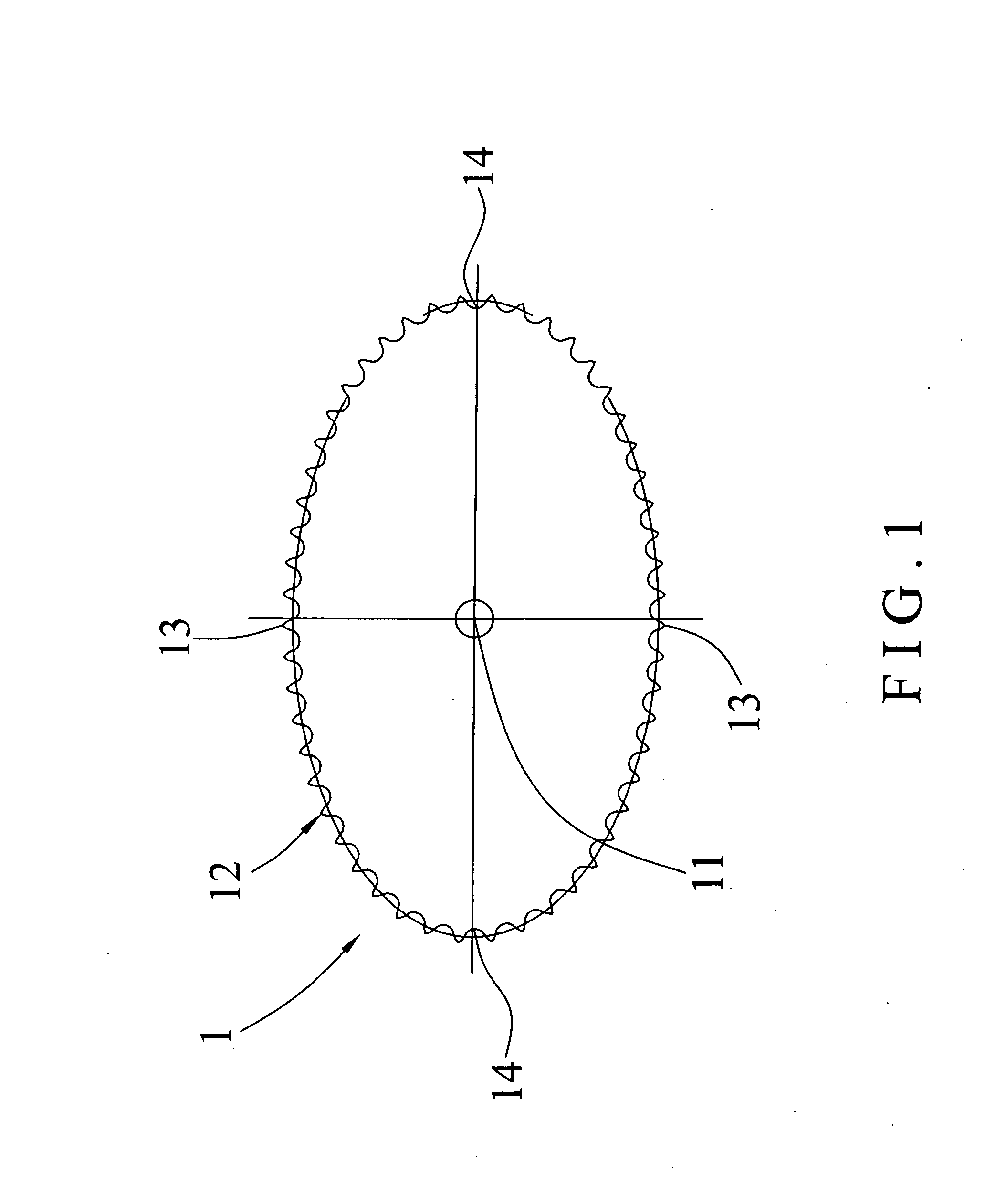
[0017] Referring to the drawings and initially to FIG. 1, a chain wheel for a bicycle in accordance with the preferred embodiment of the present invention comprises an oblong gear 1 having a flat shape.

[0018] The oblong gear 1 has a central point 11 and has a serrated periphery 12 having two opposite relatively shortest points 13 and two opposite relatively longest points 14. The periphery 12 of the oblong gear 1 has a tooth number equal to that of a circular gear 3 as shown in FIG. 3.

[0019] It is appreciated that, the periphery 12 and the central point 11 of the oblong gear 1 define a relatively shortest distance from each of the relatively shortest points 13 to the central point 11 of the oblong gear 1 and a relatively longest distance from each of the relatively longest points 14 to the central point 11 of the oblong gear 1.

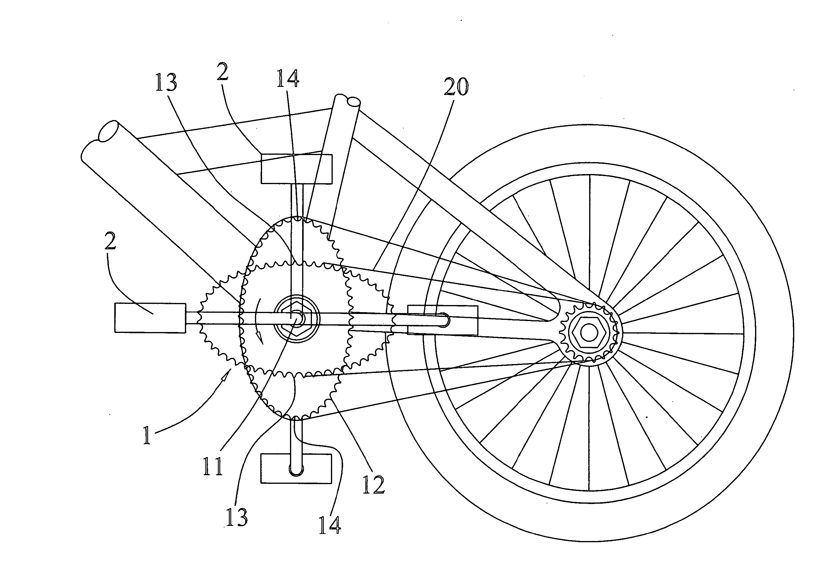
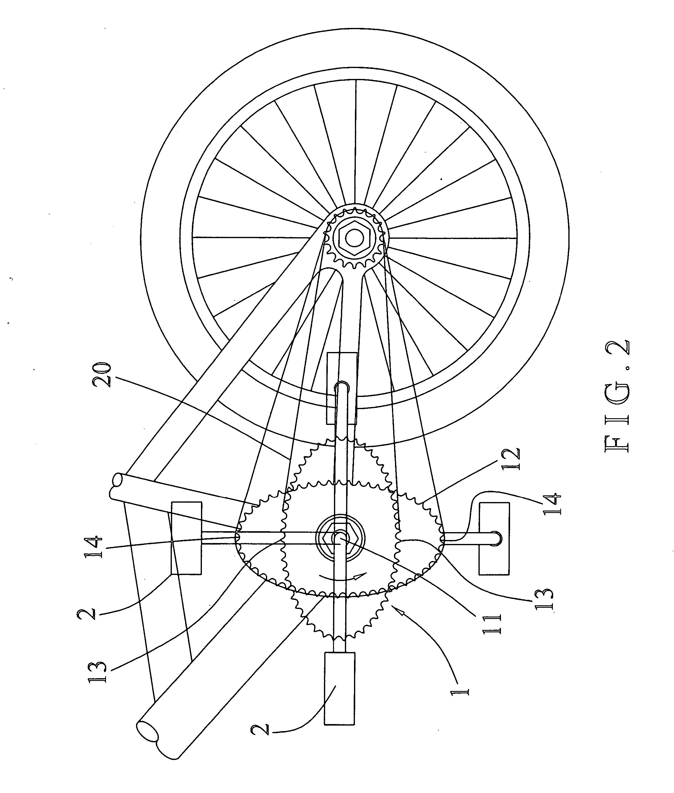
[0020] Referring to FIG. 2 with reference to FIG. 1, when the chain wheel is mounted on a bicycle, the oblong gear 1 is driven by two pedals 2 to drive and...


PUM


Abstract

A chain wheel for a bicycle includes an oblong gear having a flat shape. The oblong gear has a central point and has a periphery having two opposite relatively shortest points and two opposite relatively longest points. The periphery of the oblong gear has a tooth number equal to that of a circular gear. The oblong gear is driven by two pedals to drive and rotate a chain. Thus, the moment produced by the oblong gear has different values to compensate the different positions of the two pedals, so that the rider's legs can apply a pedaling force on the two pedals evenly and smoothly, thereby facilitating the rider pedaling the two pedals.

Description

BACKGROUND OF THE INVENTION [0001] 1. Field of the Invention [0002] The present invention relates to a chain wheel and, more particularly, to a chain wheel for a bicycle. [0003] 2. Description of the Related Art [0004] A conventional chain wheel for a bicycle in accordance with the prior art shown in FIGS. 3 and 4 comprises a circular gear 3 having a central point 31 and has a serrated periphery 32 having a plurality of peripheral points 33. The circular gear 3 has a constant radius so that the distance between each of the peripheral points 33 of the periphery 32 and the central point 31 of the circular gear 3 has a constant value. When the chain wheel is mounted on a bicycle, the circular gear 3 is driven by two pedals 4 to drive and rotate a chain 40. [0005] In practice, the two pedals 4 apply a drive force on the circular gear 3, and the circular gear 3 applies a driven force on the chain 40 so that the two pedals 4 drive the circular gear 3 to drive the chain 40 by a linkage act...

Claims


Application Information

Patent Timeline
IPC IPC(8): B62M1/02B62M1/36
CPCB62M9/00B62M2009/002B62M9/08
Inventor SHU, MING-TSAN
Owner SHU MING TSAN
Why Eureka
Try Eureka