Swaging tool with multiple pushers

Inactive Publication Date: 2001-03-13
MECH1
View PDF19 Cites 19 Cited by
  • Summary
  • Abstract
  • Description
  • Claims
  • Application Information

AI Technical Summary

Benefits of technology

The present invention provides a swaging tool for swaging axially swaged fittings on pipes, especially pipes of two inches or more in diameter. The present invention, as described in more detail below, provides a radially balanced axial force, for uniformly pushing a ring of a fitting o

Problems solved by technology

Thus, the swaging tool tends to provide the majority of axial force along the contacted portion of the pipe, which tends to create a non-uniform force distribution over the ring.
The non-uniform force distribution may cause the pipe to cock or deflect as the ring is moved over the sleeve.
This may cause gaps in the joint.
However, the inability of the tools to provide a substantially uniform axial force over the non-cradled portion of a pipe becomes problematic in large diameter bore pipes.
As a result, swaging techniques are not widely used in industrial applications requiring large diameter bore pipes, especially for pipes containing high pressure fluid flow, such as in the marine and offshore oil and gas industries.
Until now, improvements in swaging tools for large diameter bore, high pressure pipe applications have generally been seen as unnecessary since large bore pipes may be coupled together using welds, flange and bolt connections, and threaded engagements.
Although these types of connections are commonplace, they have a variety of drawbacks, which make them hig

Method used


Image

  • Swaging tool with multiple pushers
  • Swaging tool with multiple pushers
  • Swaging tool with multiple pushers

Examples


Example

Embodiments of the present invention will be described with reference to the aforementioned figures. These figures have been simplified for ease of understanding and describing the embodiments.

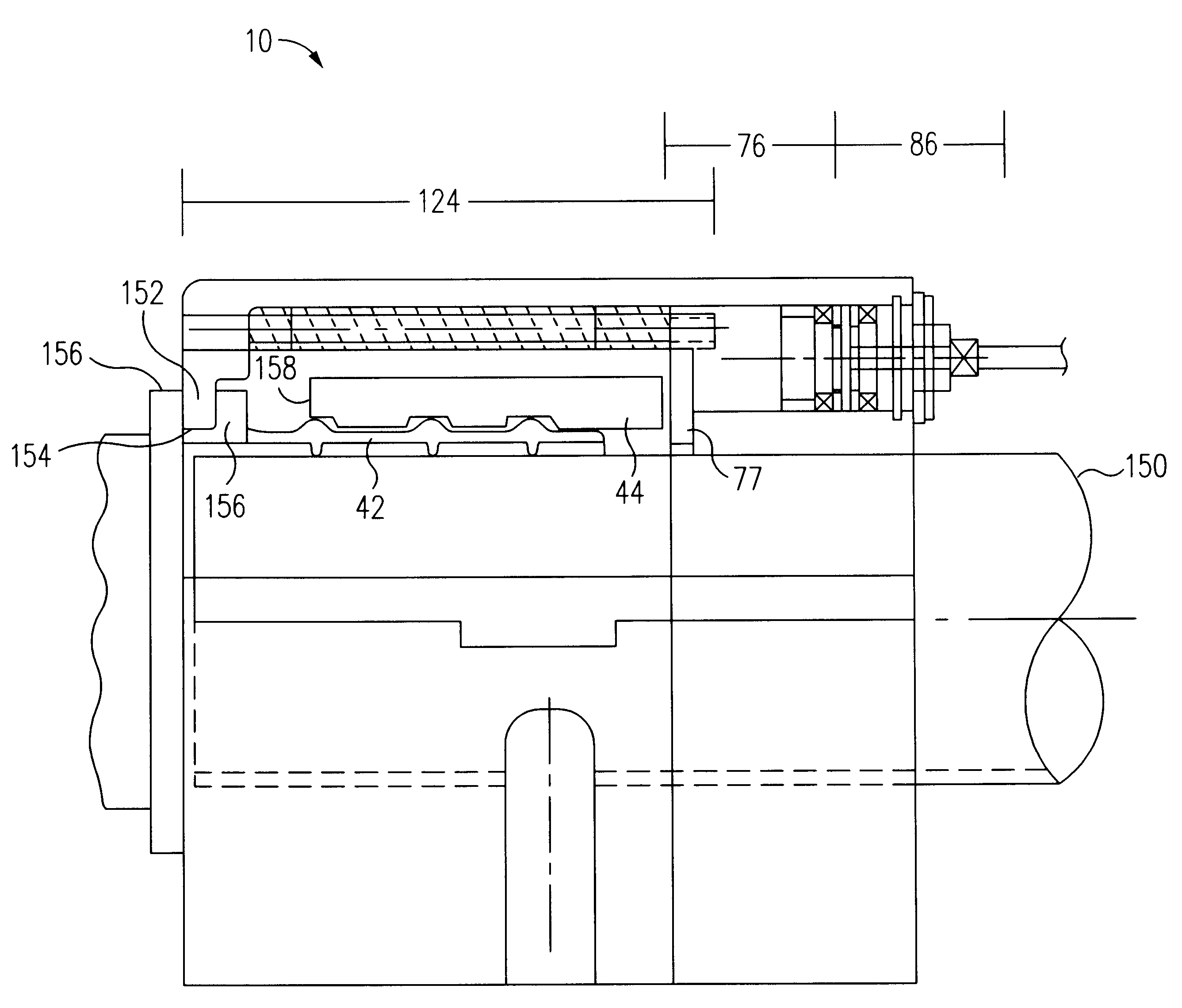
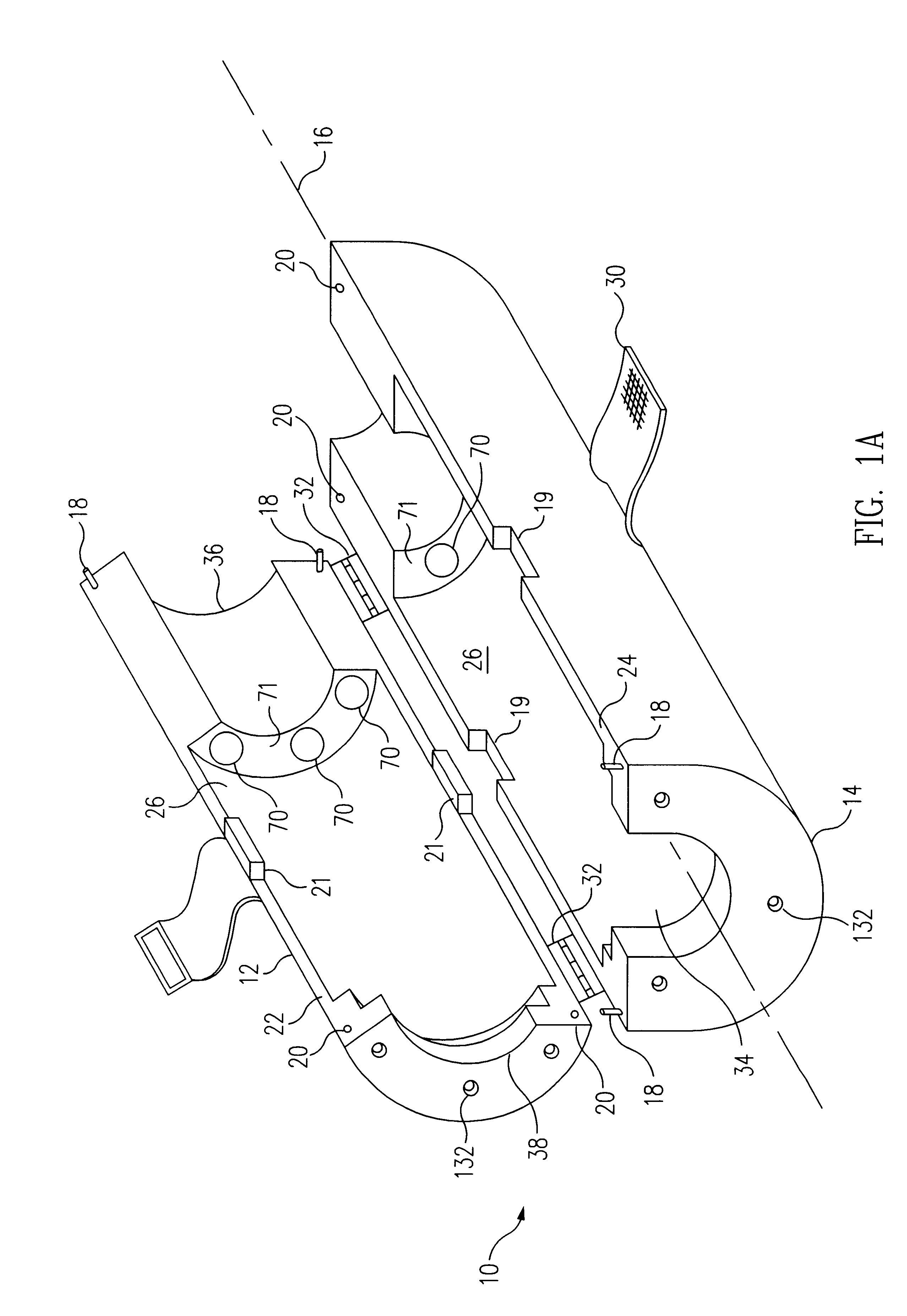
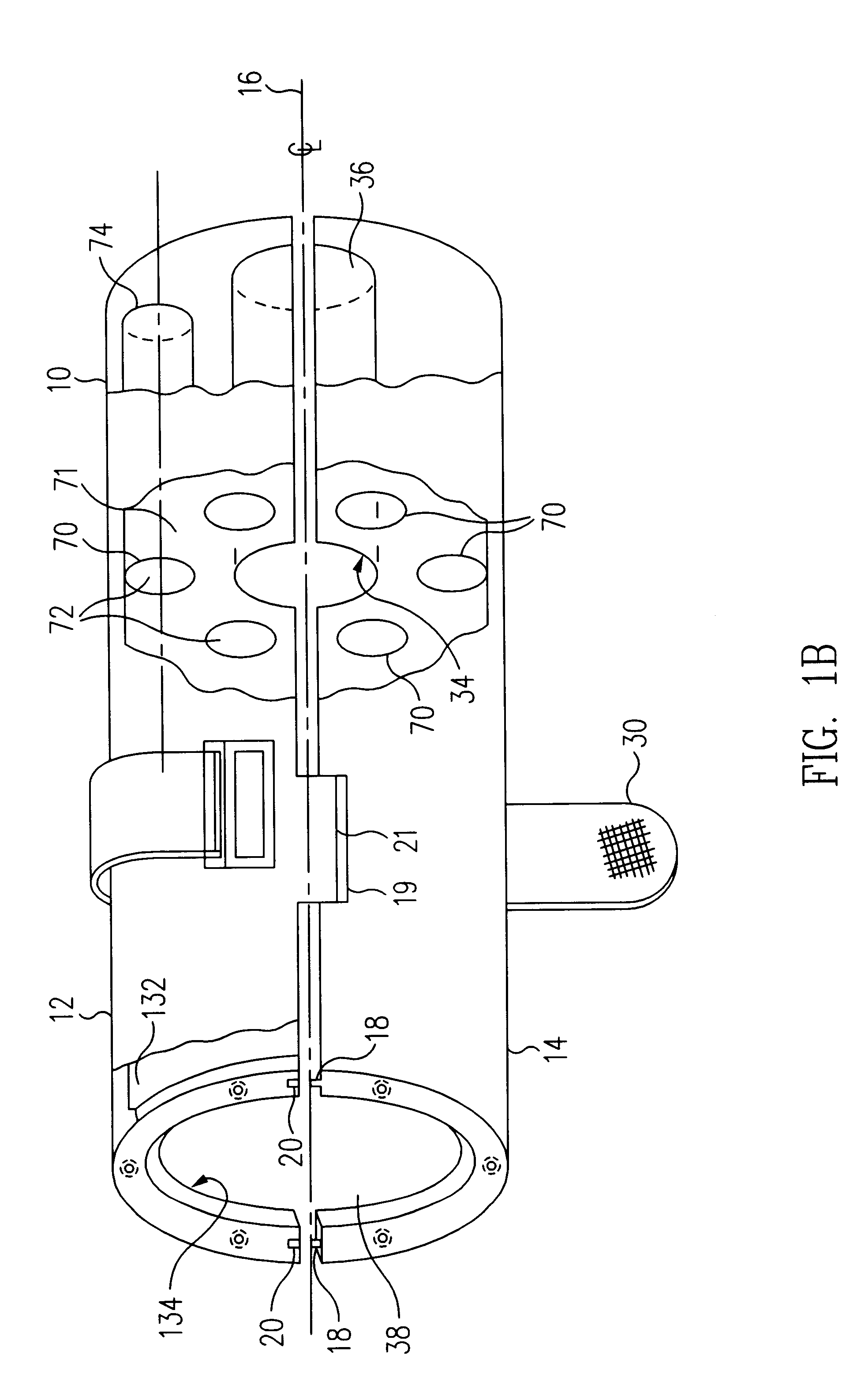
FIGS. 1A and 1B show an open perspective view and a substantially closed side view, respectively, of a swaging tool in accordance with an embodiment of the present invention. Swaging tool 10 includes a first housing section 12 and a second housing section 14. Swaging tool 10 is broadly symmetrical about a central axis 16. Thus, the description of swaging tool 10 is directed to only one housing section of the tool, with reference to the other housing section, only when necessary to describe a feature of the invention, since the other section is structurally and functionally the same. Each housing section 12 and 14, as well as many of the features included in the housing, as described below, may be formed using conventional machining and milling techniques, for example electrical discharge machi...


PUM

PropertyMeasurementUnit
Forceaaaaaaaaaa
Pressureaaaaaaaaaa
Circumferenceaaaaaaaaaa

Abstract

A swaging tool for use in swaging axially swaged fittings for joining together pipes. The present invention provides a radially balanced axial force, for uniformly pushing a ring of an axially swaged fitting over a sleeve, to swage the fitting to the pipe. The swaging tool of the present invention includes a tubular housing, having an inner surface, which defines a bore. The bore is configured to receive a pipe section having an axially swaged fitting placed thereon in preparation for swaging. Preferably, the housing may be split lengthwise into two opposed sections, such that when the two sections are brought together, the sections completely surround a portion of the pipe section and the fitting. Each housing section is provided a plurality of pusher assemblies, each pusher assembly may preferably be connected to a source of hydraulic pressure, which when activated moves the pusher assembly axially to provide the axial force necessary for swaging the fitting. Each pusher assembly is made to uniformly contact the ring with a substantially equal amount of force, such that the ring is moved axially over the sleeve, which causes a radial force to be applied to the sleeve to swage the sleeve to the pipe section.

Description

1. Field of the InventionThis invention relates to swaging tools for use with swage fittings, and more particular to a swaging tool for swaging axially swaged fittings.2. Description of the Related ArtFittings of various types are commonly used to couple tubes and pipes for a variety of applications. For example, in the aerospace industry, swage fittings couple hydraulic lines, fuel lines, and the like used to convey fluids in aircraft and other vehicles. Swage fittings also couple pipes, tubes, and conduits (hereinafter collectively "pipes") that transport fluids in the marine, petroleum, and chemical industries. The coupling generally involves inserting pipe ends into a cylindrical sleeve of the fitting, and then swaging the fitting to the pipe using a swaging tool, to provide a fluid-tight or hermetic seal between the pipes. The swaging operation, generally requires the application of a radial force that deforms a portion of the pipe and the sleeve. The radial force may be applie...

Claims


Application Information

Patent Timeline
IPC IPC(8): B25B27/02B25B27/10
CPCB25B27/10Y10T29/53996Y10T29/5367Y10T29/5383
Inventor SURESH, SRINIVAS B.
Owner MECH1
Why Eureka
Try Eureka