
Electrical tool assembly

a technology of electric tools and metal contacts, which is applied in the direction of electric power, transportation and packaging, electric vehicles, etc., can solve the problems of unstable contact between the metal contacts of the electrical tool and the metal contacts, and the inability to keep the metal contacts of the battery charger positively in contact, so as to achieve quick and accurate positioning

Inactive Publication Date: 2007-10-25
MOBILETRON ELECTRONICS
View PDF2 Cites 5 Cited by
  • Summary
  • Abstract
  • Description
  • Claims
  • Application Information

AI Technical Summary

Benefits of technology

[0008] The present invention has been accomplished under the circumstances in view. It is therefore one object of the present invention to provide an electrical tool assembly, which comprises an electrical tool and a charger. The electrical tool can quickly and accurately be positioned on the charger for enabling the charging circuit of the charger to charge the battery of the electrical tool positively.

Problems solved by technology

According to the aforesaid design, it is difficult to position the electrical tool on the battery charger quickly.
Further, improper positioning of the electrical tool on the battery charger results in unstable contact between the metal contacts of the electrical tool and the metal contacts of the battery charger, i.e., the metal contacts of the electrical tool cannot be kept in contact with the metal contacts of the battery charger positively if the electrical tool is not accurately positioned on the battery charger.

Method used


Image

  • Electrical tool assembly
  • Electrical tool assembly
  • Electrical tool assembly

Examples


Embodiment Construction

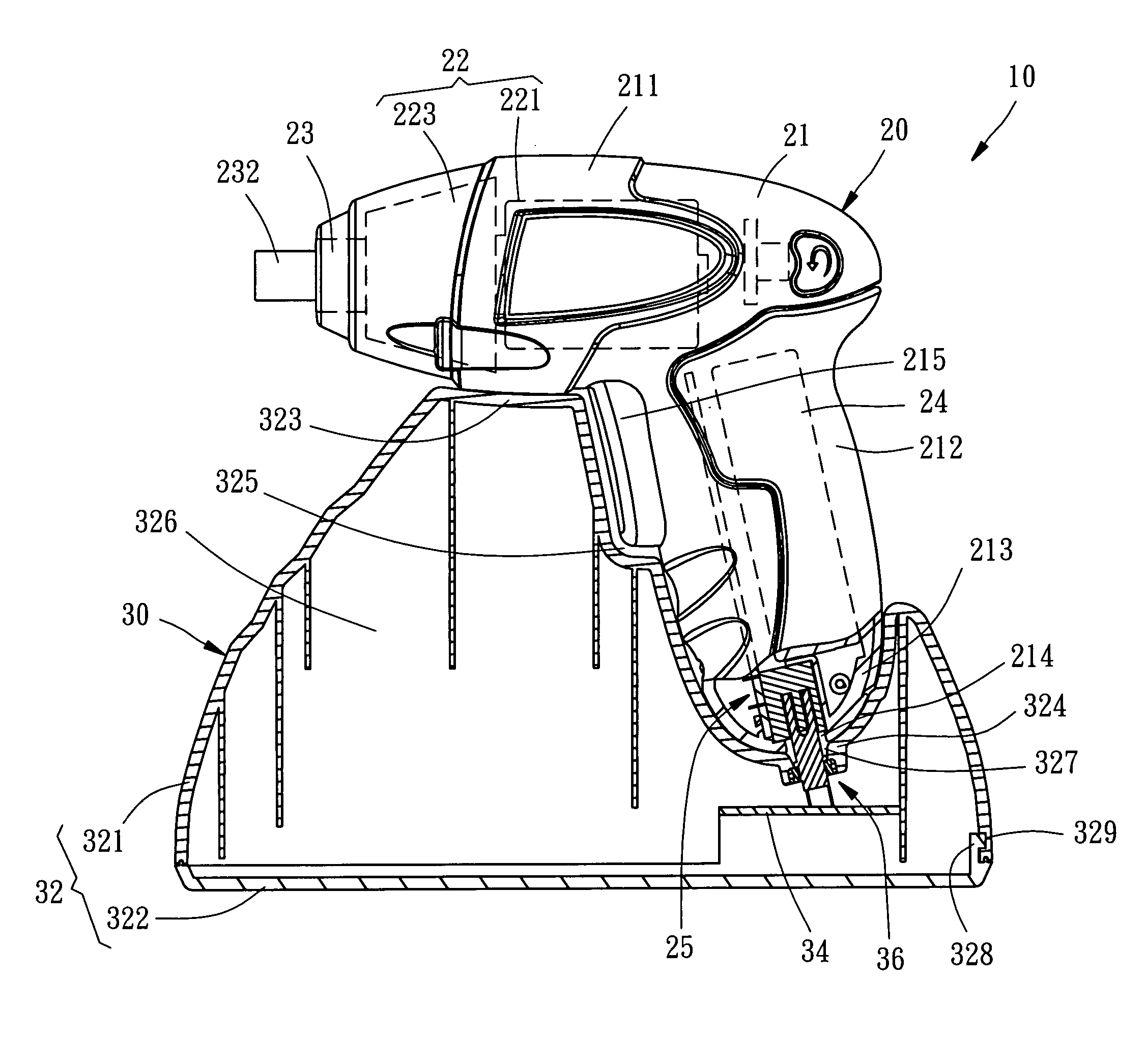
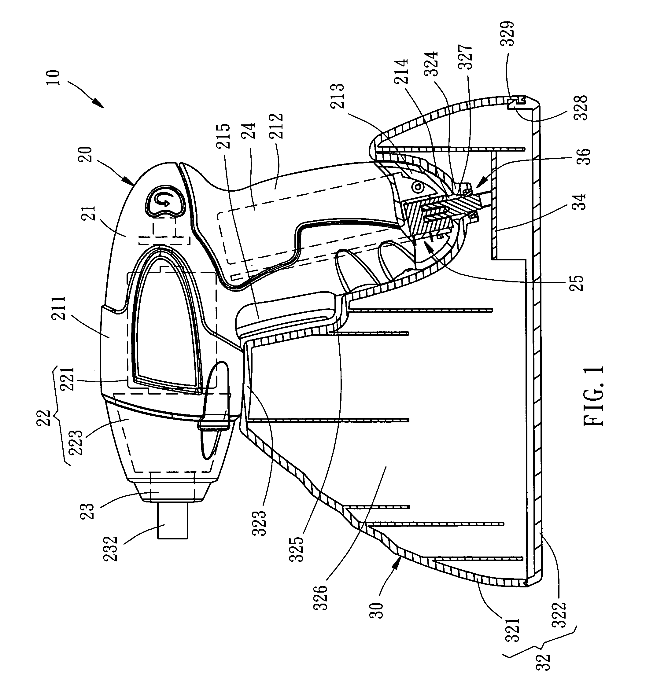
[0015] Referring to FIGS. 1-4, an electrical tool assembly 10 in accordance with a preferred embodiment of the present invention is shown comprising an electrical tool 20 and a charger 30.

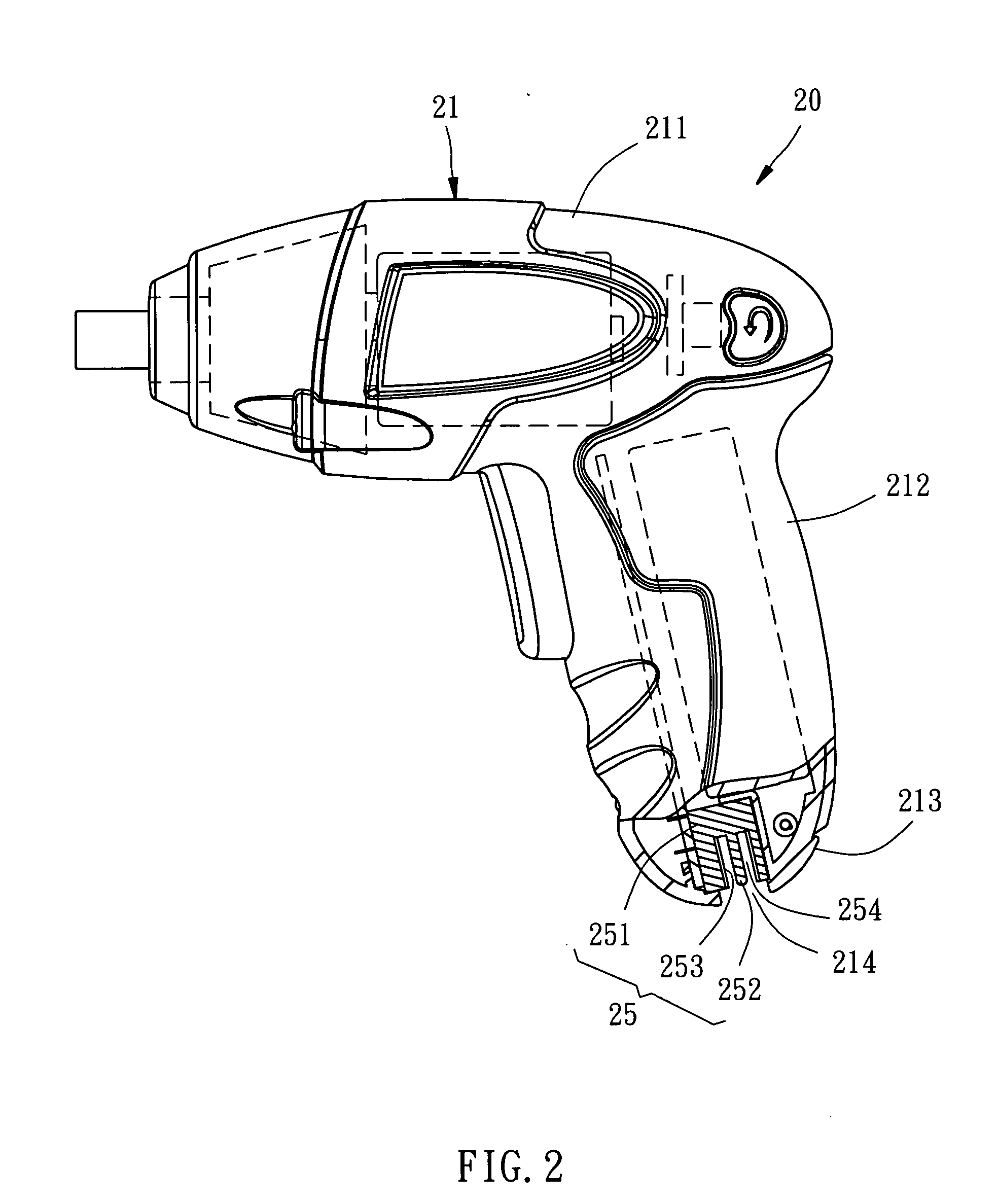
[0016] The electrical tool 20 comprises a housing 21, a power drive 22, a tool-holding member 23, a rechargeable battery 24, and a charging terminal 25.

[0017] The housing 21 comprises a body 211 and a handle 212. The handle 212 extends outwards from one side of the body 211 at a predetermined angle. The rear end of the handle 212 is gradually reducing in diameter and smoothly arched, configuring an insertion portion 213. The insertion portion 213 has an opening 214 at the bottom side. Further, a trigger 215 is mounted on the handle 212 for starting the electrical tool 20.

[0018] The power drive 22 is mounted inside the body 211 of the housing 21, comprising a motor 221 and a transmission gear set 223.

[0019] The tool-holding member 23 is mounted in one side of the body 211 of the housing 21 remot...


PUM


Abstract

An electrical tool assembly includes a battery-operated electrical tool, which has a housing and a charging terminal mounted in an insertion portion of the housing, and a charger, which has a receptacle fitting the contour of the insertion portion for the insertion of the insertion portion in a predetermined direction, a charging terminal for receiving the charging terminal of the electrical tool to charge the rechargeable battery of the battery-operated electrical tool, and a recessed seat for holding a body of the housing of the electrical tool in position upon insertion of the insertion portion into the receptacle.

Description

BACKGROUND OF THE INVENTION [0001] 1. Field of the Invention [0002] The present invention relates to electrical tools and more particularly, to an electrical tool assembly comprising a rechargeable electrical tool and a battery charger for charging the electrical tool. [0003] 2. Description of the Related Art [0004] A commercial electrical tool is known having a rechargeable battery mounted inside the housing thereof to provide the necessary working power. When the power of the battery is used up, a battery charger must be used to charge the rechargeable battery to the saturated status. [0005] The aforesaid electrical tool has a pair of metal contacts exposed to the outside of the housing and respectively electrically connected to the positive and negative poles of the battery. Further, a battery charger for charging the aforesaid electrical tool has two power output metal contacts corresponding to the metal contacts of the electrical tool. When the electrical tool is set in the bat...

Claims


Application Information

Patent Timeline
Patent Type & Authority Applications(United States)
IPC IPC(8): H02J7/00
CPCH02J7/0044
Inventor HUANG, WEN-HAI
Owner MOBILETRON ELECTRONICS
Learn More