
3-D projection full color multimedia display

a multimedia display and 3d projection technology, applied in optics, instruments, electrical equipment, etc., can solve the problems of poor quality, impaired 3d effect, unappealing to the typical consumer,

Active Publication Date: 2007-10-25
CHRISTIE DIGITAL SYST USA INC +1
View PDF15 Cites 91 Cited by
  • Summary
  • Abstract
  • Description
  • Claims
  • Application Information

AI Technical Summary

Benefits of technology

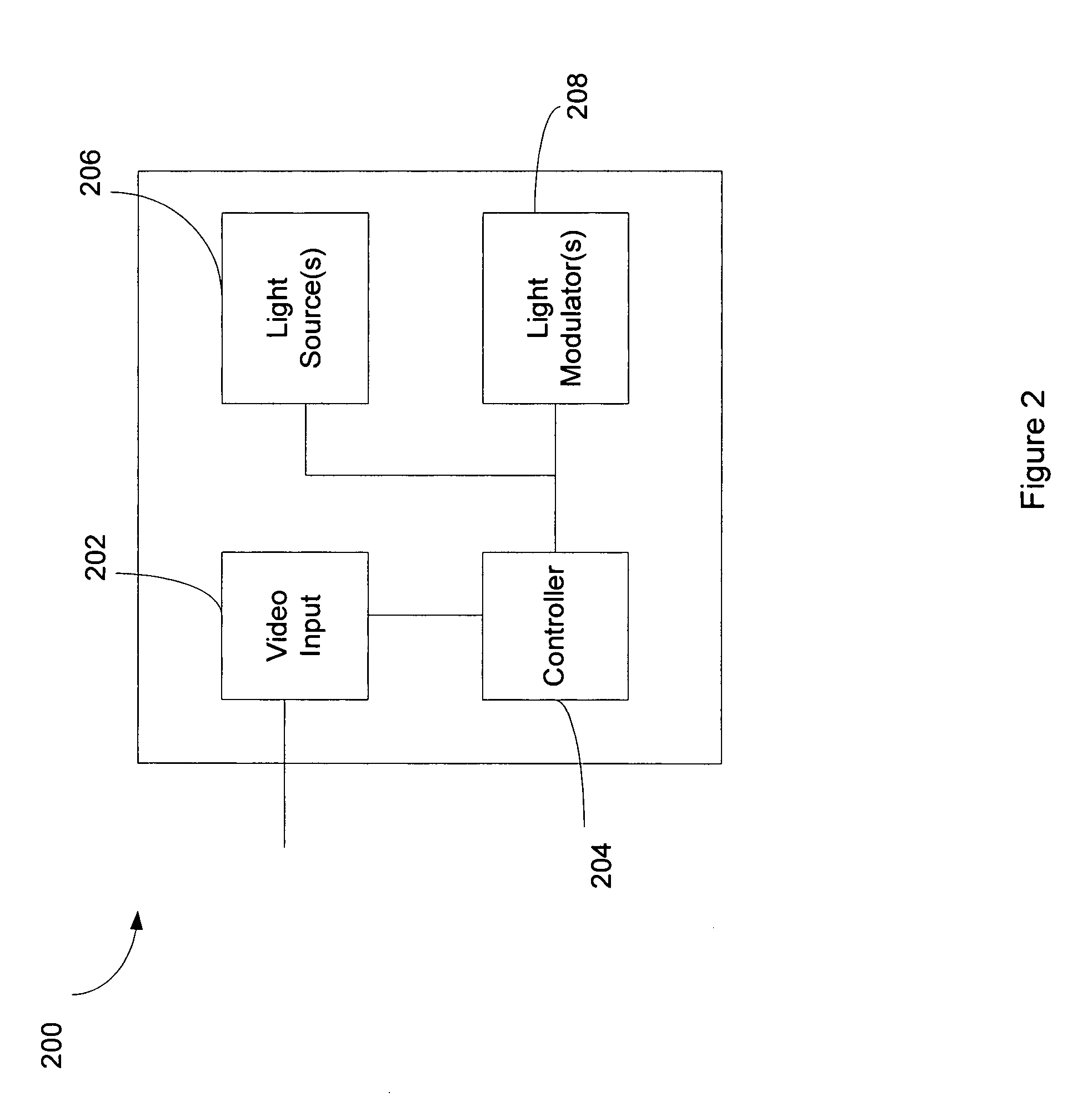
The invention relates to a method and system for displaying a three-dimensional image. The method involves displaying two series of images, one for the left eye and one for the right eye, using different colors. The viewer wears special glasses with filters for each eye, which filter out the corresponding color in the first series of images. The system includes a light modulator that alternates between the two series of images, and a processor for controlling the modulator. The system also includes viewing glasses with filters for each eye that block the colors emitted by the light sources. The technical effects of the invention include improved depth perception and reduced eye fatigue.

Problems solved by technology

However, color filters which fully reject the undesired image are difficult to make, with the result that the 3-D effect is impaired.
A significant disadvantage therefore remains in that the image is essentially interpreted in the brain as a black and white image or is only capable of producing drab colors at best, which is unappealing to the typical consumer.
The images are generally of poor quality with perceptible shadowing, and may cause discomfort to the viewer, such as eye fatigue and / or nausea.
This method produces high-quality images, but disadvantageously also requires two projectors, goggles with high-quality polarizing filters for viewing, and a special polarization-maintaining projection screen.
Moreover, the 3-D image will wash out if the viewer tilts his / her head too much or moves around too far.
This process is complicated and expensive, and requires special equipment for broadcasting the trigger signals to the electro-optical glasses worn by each user.
However, the conventional methods cannot be used with, for example, rear-projection television (RPTV) sets, because the polarization becomes completely random when the image passes through the screen of the RPTV and as a result, the 3-D effect gets lost.

Method used


Image

  • 3-D projection full color multimedia display
  • 3-D projection full color multimedia display
  • 3-D projection full color multimedia display

Examples


Embodiment Construction

[0024]To provide an overall understanding of the invention, certain illustrative embodiments will now be described, including various apparatus and methods for forming three-dimensional images. However, it will be understood by one of ordinary skill in the art that the apparatus and methods described herein may be adapted and modified as is appropriate for the application being addressed and that the systems and methods described herein may be employed in other suitable applications, and that such other additions and modifications will not depart from the scope hereof.

[0025]Systems and methods are described that can be used to produce a full-color projection image on a non-polarization maintaining screen, such as a RPTV. The systems and methods are based on the concept that almost any point in color space is accessible by a combination of three distinct colors, red (R), green (G), and blue (B). An additive color system involves light emitted directly from a source or illuminant of s...


PUM


Abstract

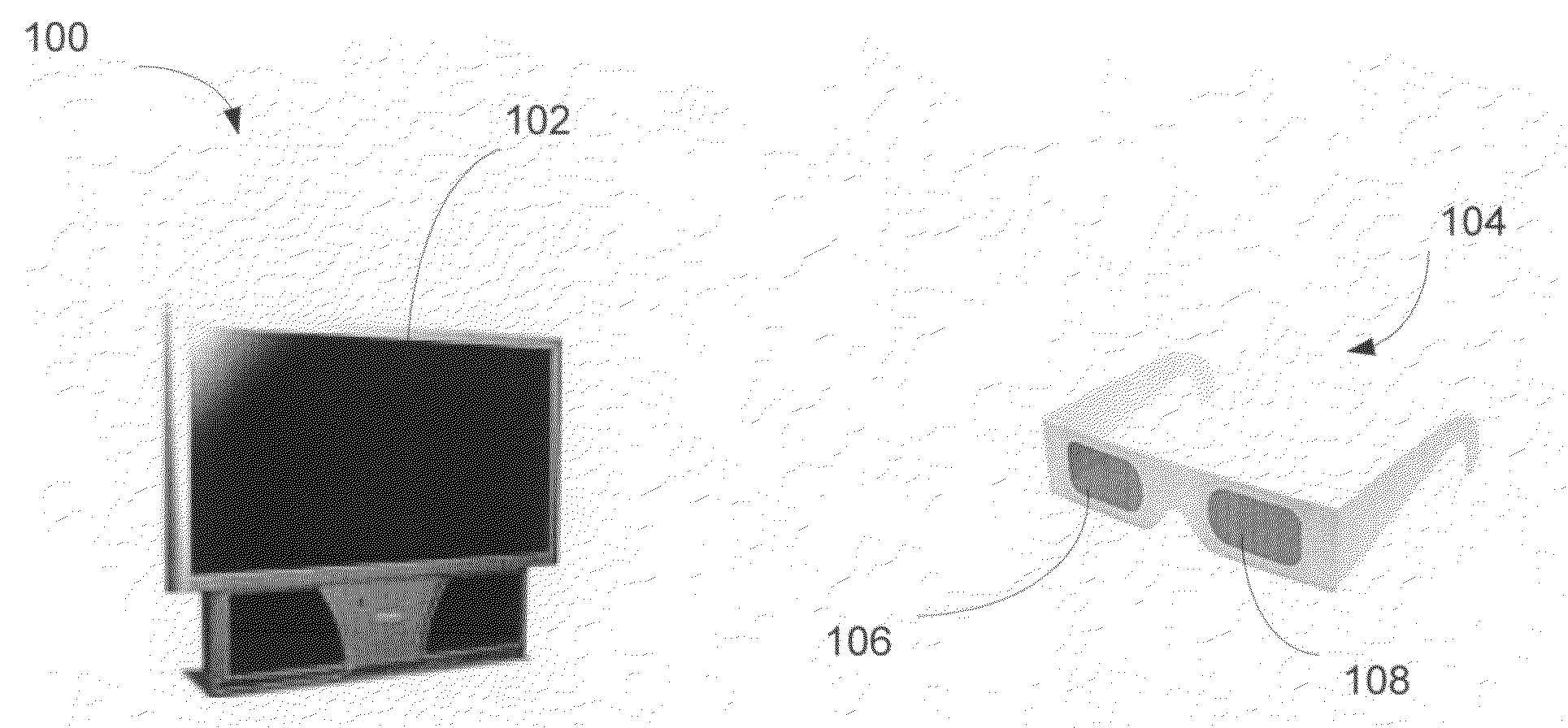
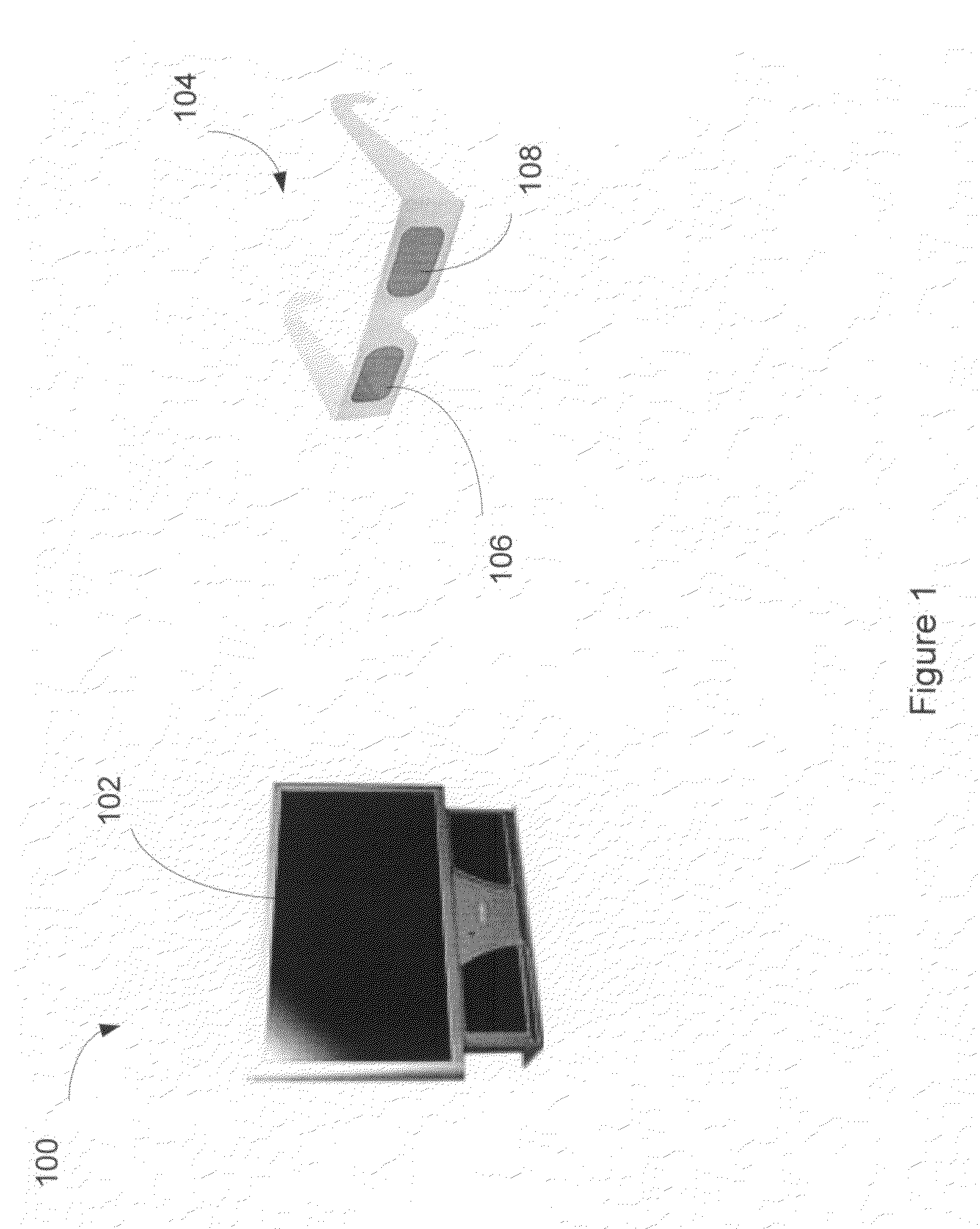
Methods and systems are described herein which produce polarization-independent full color images suitable for rear-projection television sets and other multimedia displays. The system uses illumination with R, G, B light from two different light sources for each color. A viewer wears glasses with narrowband optical filters, preferably holographic filters. The R, G, B light from the light sources is slightly offset at each of the 3 emission wavelengths, with one set of R, G, B light being filtered by the holographic filter in front of the left eye of the, and the other set of R, G, B light being filtered by the holographic filter in front of the viewer's right eye.

Description

CROSS-REFERENCE TO RELATED APPLICATION[0001]This application claims the benefit of U.S. Provisional Application Ser. No. 60 / 794,669, filed Apr. 25, 2006, the entire contents of which are incorporated herein by reference.BACKGROUND OF THE INVENTION[0002]Various techniques have been used in the past to produce stereoscopic (three-dimensional) images for motion pictures or television. In general, these techniques involve two camera systems in which two different pictures are taken from slightly different camera angles and locations. The object is to simulate the manner in which depth is perceived by a pair of human eyes, which are themselves slightly offset from each other and thus view images at slightly different angles. The two camera images are superimposed and presented to the viewer simultaneously on a television or movie screen. The images are then separated in some fashion for the viewer so that one eye sees only one image, and the other eye sees only the other image.[0003]One ...

Claims


Application Information

Patent Timeline
Patent Type & Authority Applications(United States)
IPC IPC(8): G02B27/22
CPCG02B27/2264H04N13/0422G02B27/2207H04N13/0427H04N13/0431H04N13/0459G02B27/2228H04N13/324H04N13/365H04N13/334H04N13/363G02B30/23G02B30/34G02B30/24
Inventor KARAKAWA, MASAYUKI
Owner CHRISTIE DIGITAL SYST USA INC
Learn More