Real-time services network quality control

a real-time services and network quality technology, applied in the field of real-time services network quality control, can solve the problems of not ensuring the reliability of data transfer, snmp does not provide even the basic troubleshooting information, and may limit the ability of network managers to lose data

Inactive Publication Date: 2007-10-25
TITUS TIMOTHY G
View PDF5 Cites 54 Cited by
  • Summary
  • Abstract
  • Description
  • Claims
  • Application Information

AI Technical Summary

Benefits of technology

This patent describes a software program called VOIP Quality Monitor that allows users to measure the quality of their Voice Over IP (VoIP) calls through a web-based interface. The program uses standard protocols to gather information from multiple devices on the network, including routers and switches. This data helps identify areas with poor connectivity or performance issues. Users can then select specific equipment and settings to improve call quality. Overall, this tool makes it easier for administrators to manage and optimize VoIP networks.

Problems solved by technology

The technical problem addressed in this patent text is the need for more effective ways to monitor network performance issues such as latency, jitter, and packet loss. Conventional testing techniques often involve sentencing traffic and analyzing logs, leading to waste of network resources. Additionally, there is no easy way to quickly detect and troubleshoot malfunctions in real-time communication circuits.

Method used


Image

  • Real-time services network quality control
  • Real-time services network quality control
  • Real-time services network quality control

Examples


Embodiment Construction

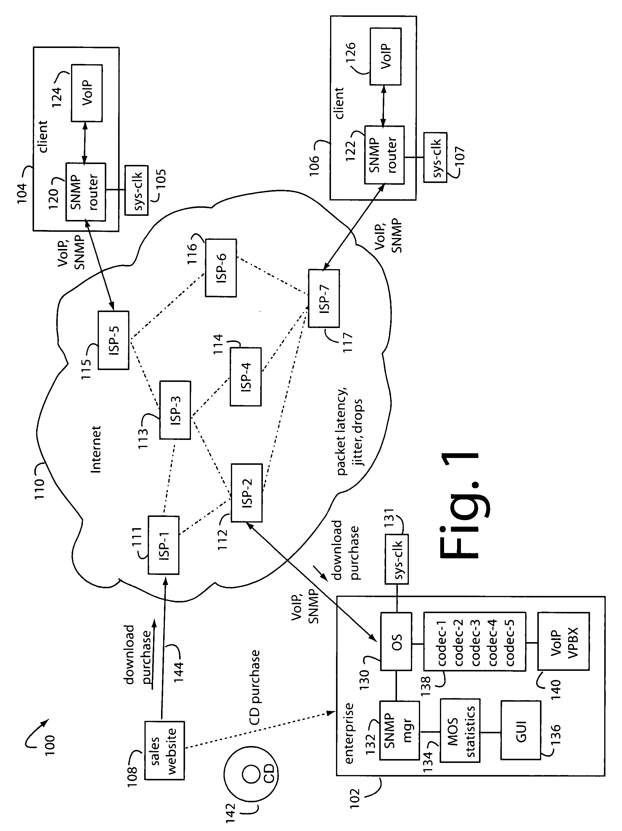
[0035]FIG. 1 shows a network quality assessment system embodiment of the present invention, and is referred to herein by the general reference numeral 100. In this instance, the system 100 supports a virtual private branch exchange (VPBX) implementation that allows a business enterprise to incorporate PBX-type telephone extensions at employee homes and / or remote branch offices. Such VPBX requires higher than usual network connection quality to support inter-company communications. Voice over Internet Protocol (VOIP) as well as video services can be accommodated. The system 100 comprises a business enterprise 102 with many remote clients, e.g., 104 and 106. A sales website 108 is present on the Internet 110, which includes many inter-meshing Internet service providers (ISP's), e.g., ISP-1 to ISP-7, 111-17. Each client 104, 106, includes a commercial, off-the-shelf wireless router 120, 122, with SNMP support, and a VoIP port 124, 126.

[0036]The enterprise 102 includes an operating syst...


PUM


Abstract

A network quality control system includes a user control console to probe, calculate, and display the quality of an enterprise's network connections to remote SNMP managed devices supporting real-time services like VoIP. Traceroute-like messages are sent to each remote SNMP managed device to report on the path, and hop latency, jitter, and packet losses. MOS scores are computed to indicate performance with a variety of available codec's. Empty test packets used simply to probe network quality are not used. Instead, SNMP messages that carry valuable information or commands for other purposes are gleaned of timing information so the MOS quality scores can be calculated in background.

Description


Claims


Application Information

Patent Timeline
Owner TITUS TIMOTHY G
Why Eureka
Try Eureka