Illuminated power receptacle

a technology of illumination and power receptacles, applied in the direction of connection contact material, tumbler/rocker switch, coupling device connection, etc., can solve the problems of difficult locating of people who are blind have difficulty locating receptacles and orienting plugs, and the process of locating and orienting plugs can be frustrating especially for people with impaired vision, so as to reduce frustration, easy to locate and identify, accurate and rapid

Inactive Publication Date: 2007-11-01
JEMSICO
View PDF17 Cites 16 Cited by
  • Summary
  • Abstract
  • Description
  • Claims
  • Application Information

AI Technical Summary

Benefits of technology

[0013] Standard receptacles have the simple task of providing power to a standard plug. An enhanced power outlet system will additionally allow the user to easily locate and identify the receptacle and orient the plug for accurate and rapid insertion. Objects and advantages of the illuminated power receptacle system include incorporating visual or tactical means to aid the user in locating and inserting plugs into receptacles to assist people with impaired vision, decreasing frustration, improving time utilization, and potentially decreasing risk of accidental electrocution. The population assisted by this device is large and includes people with presbyopia, myopia, hyperopia, amblyopia, and scotoma, and who are blind.

Problems solved by technology

Polarized plugs and the small size of plugs, often makes locating the receptacle and orienting the plug difficult.
Additionally, people who are blind have difficulty locating receptacles and orienting plugs.
The process of locating a receptacle and orienting and inserting the plug can be frustrating especially for people with impaired vision.
Interior prong-hole lighting may not project well through the prong-holes, especially when the receptacle is viewed from an angle as is commonly done and thus may not provide the user with adequate information to efficiently orient the plug.

Method used


Image

  • Illuminated power receptacle
  • Illuminated power receptacle
  • Illuminated power receptacle

Examples


Embodiment Construction

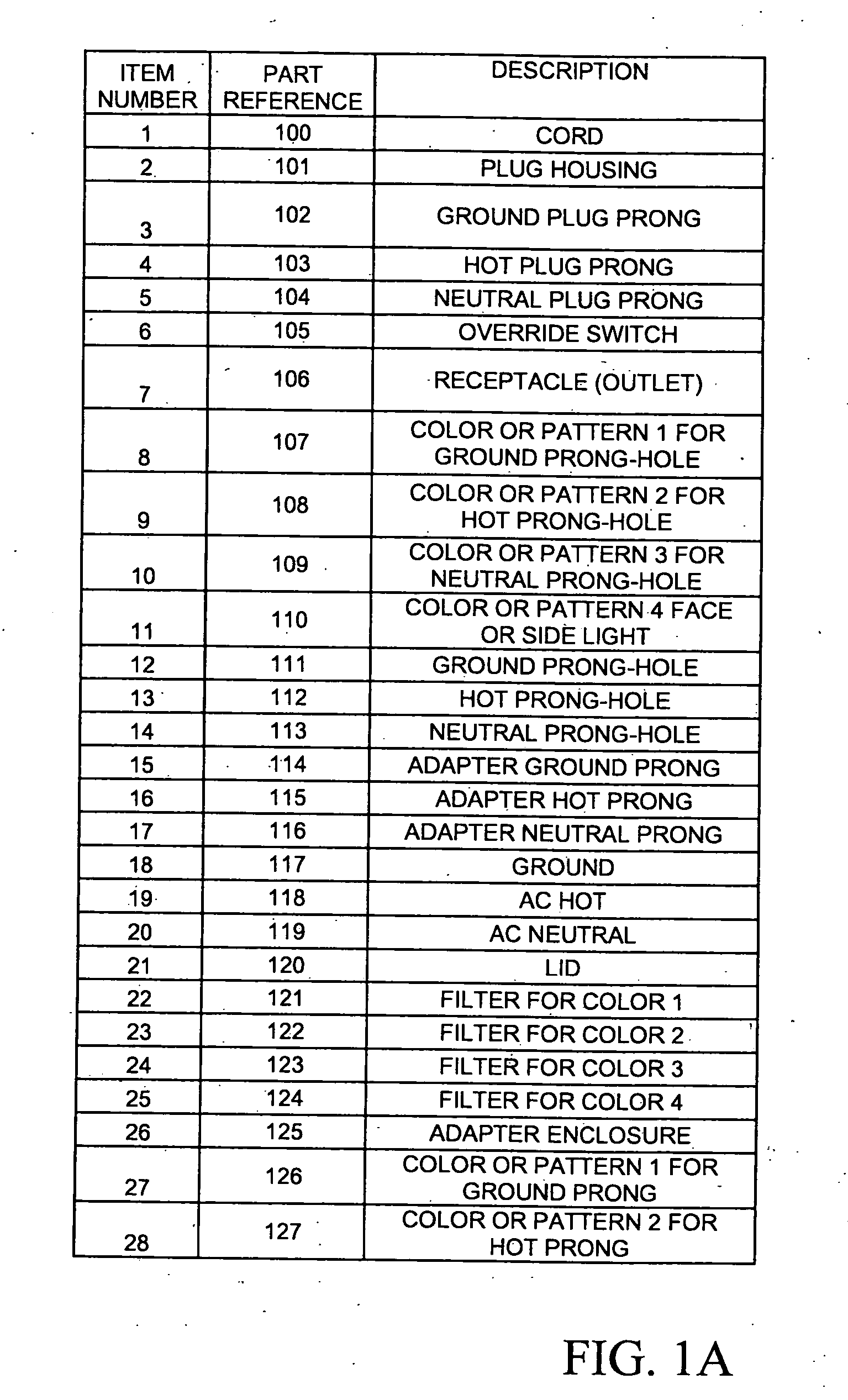
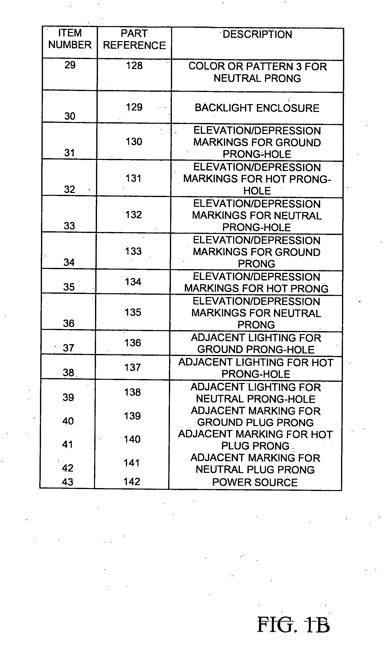
[0035] Referring now to the drawings, FIG. 1A and FIG. 1B contain a table of the descriptions of the designators for FIG. 2 through FIG. 15.

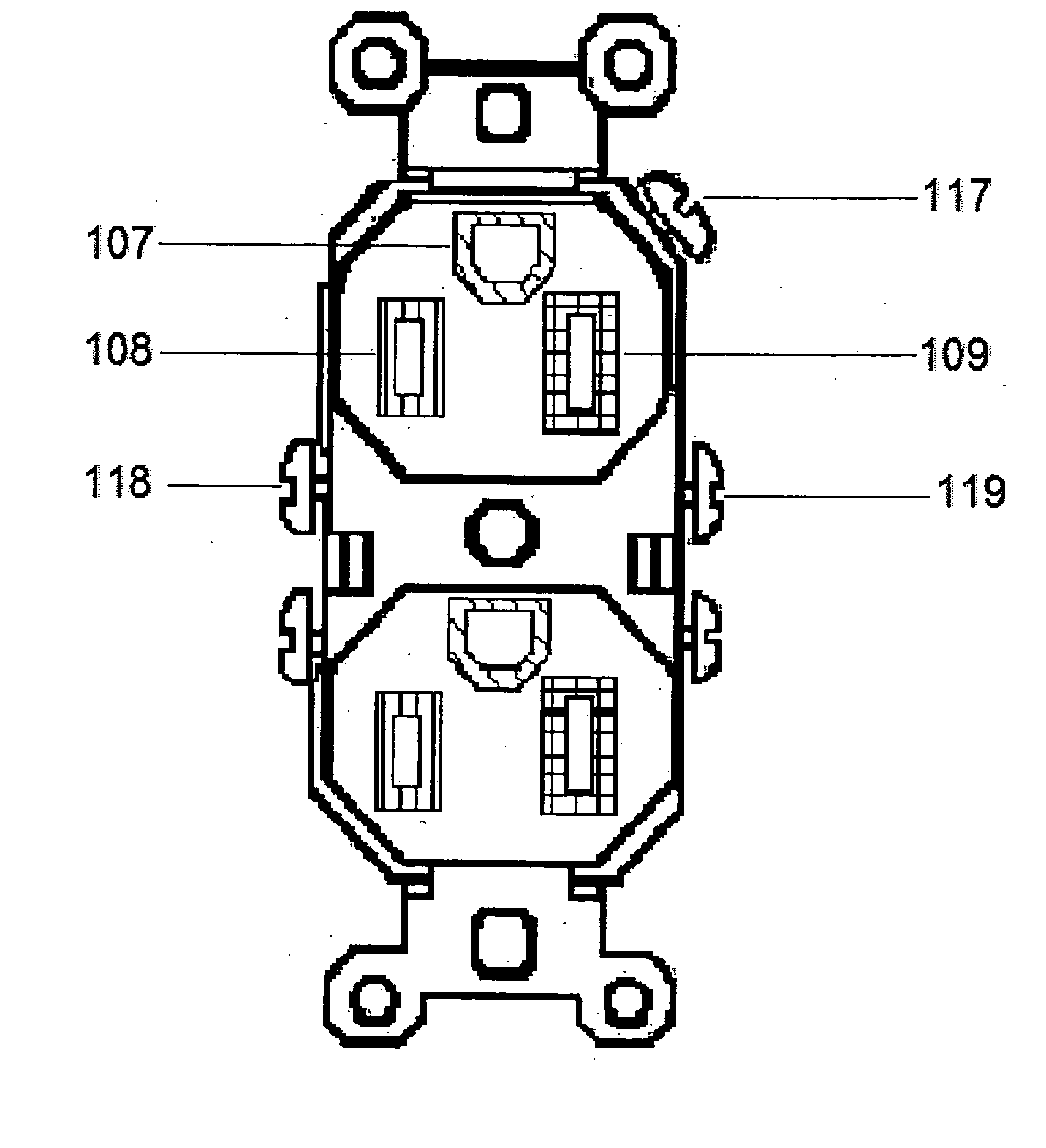
[0036]FIG. 2 is a front view of an embodiment of the Illuminated Power Receptacle with color lighting surrounding the prong-holes. The enclosure 125 contains a duplex receptacle 106. Regions 107, 108 and 109 represent the lighting scheme surrounding the prong-holes. The duplex receptacle 106 has a face lighting scheme and marking pattern 110. The lighting scheme has an on / off switch 105. This view may be of either an external (as in FIG. 13) or internal wall receptacle.

[0037]FIG. 3 is a front view of an embodiment of the Illuminated Power Receptacle with color markings surrounding the prong-holes. The enclosure 125 contains regions 107, 108 and 109 that represent the marking scheme around the prong-holes. It also contains the face lighting scheme and marking pattern 110. This view may be of either an external (as in FIG. 13) or internal wall r...


PUM


Abstract

The present invention relates to the field of enhanced electrical power receptacles and associated plugs. Specifically it relates to power receptacles that are easy to identify and use. It achieves these features with a receptacle that has the individual prong-holes identified and differentiated with light source or markings in a scheme that allows the user to quickly locate and identify the proper prong-holes. The associated plug can be labeled with markings for orientation. The receptacle lighting or pattern scheme will help the user easily locate the receptacle and orient the associated plug for accurate and rapid insertion.

Description

[0001] This application claims the benefit of U.S. Provisional Patent Application Ser. No. 60 / 761,228, filed Jan. 23, 2006, which is hereby incorporated by reference in its entirety.FIELD OF THE INVENTION [0002] This invention relates to an enhanced receptacle using a lighting or marking scheme to aid the user in locating the receptacle and with proper plug insertion. BACKGROUND OF THE INVENTION [0003] Plugging electrified objects into receptacles is an everyday occurrence. Polarized plugs and the small size of plugs, often makes locating the receptacle and orienting the plug difficult. This is particularly true for people with low vision and the vast majority of the middle-aged and elderly people with presbyopia. Additionally, people who are blind have difficulty locating receptacles and orienting plugs. Low vision is defined as vision that is impaired and cannot be corrected by way of surgery, glasses, or contacts. Presbyopia is a visual condition that develops in most middle-aged...

Claims


Application Information

Patent Timeline
Patent Type & Authority Applications(United States)
IPC IPC(8): H01R13/46
CPCH01R13/465H01R13/652H01R13/7172H01R2103/00H01R24/30H01R24/78H01R13/7175
Inventor BERG, MICHEL J.BARRANTES, JAVIER M.BRUEMMER, ERIN M.LAPICZAK, IGAR J.NANDURI, SASHANK
Owner JEMSICO
Why Eureka
Try Eureka