Head position control method, head position control device, and disk device

Active Publication Date: 2007-11-01
KK TOSHIBA
View PDF18 Cites 4 Cited by
  • Summary
  • Abstract
  • Description
  • Claims
  • Application Information

AI Technical Summary

Benefits of technology

[0033]Since the state information is generated using an estimated gain determined from a disturbance model defined by a transfer function of which denominator is a numerator of a filter in which degrees of the denominator and numerator for shaping the sensitivity fun

Problems solved by technology

In this positioning control, it is known that disturbance influences positioning accuracy.
In other words, as the recording density of the disk device increases, the influence of external vibration on the positioning accuracy of the head can no longer be ignored.
However along with adapting to a w

Method used


Image

  • Head position control method, head position control device, and disk device
  • Head position control method, head position control device, and disk device
  • Head position control method, head position control device, and disk device

Examples


Example

First Embodiment of Disturbance Observer

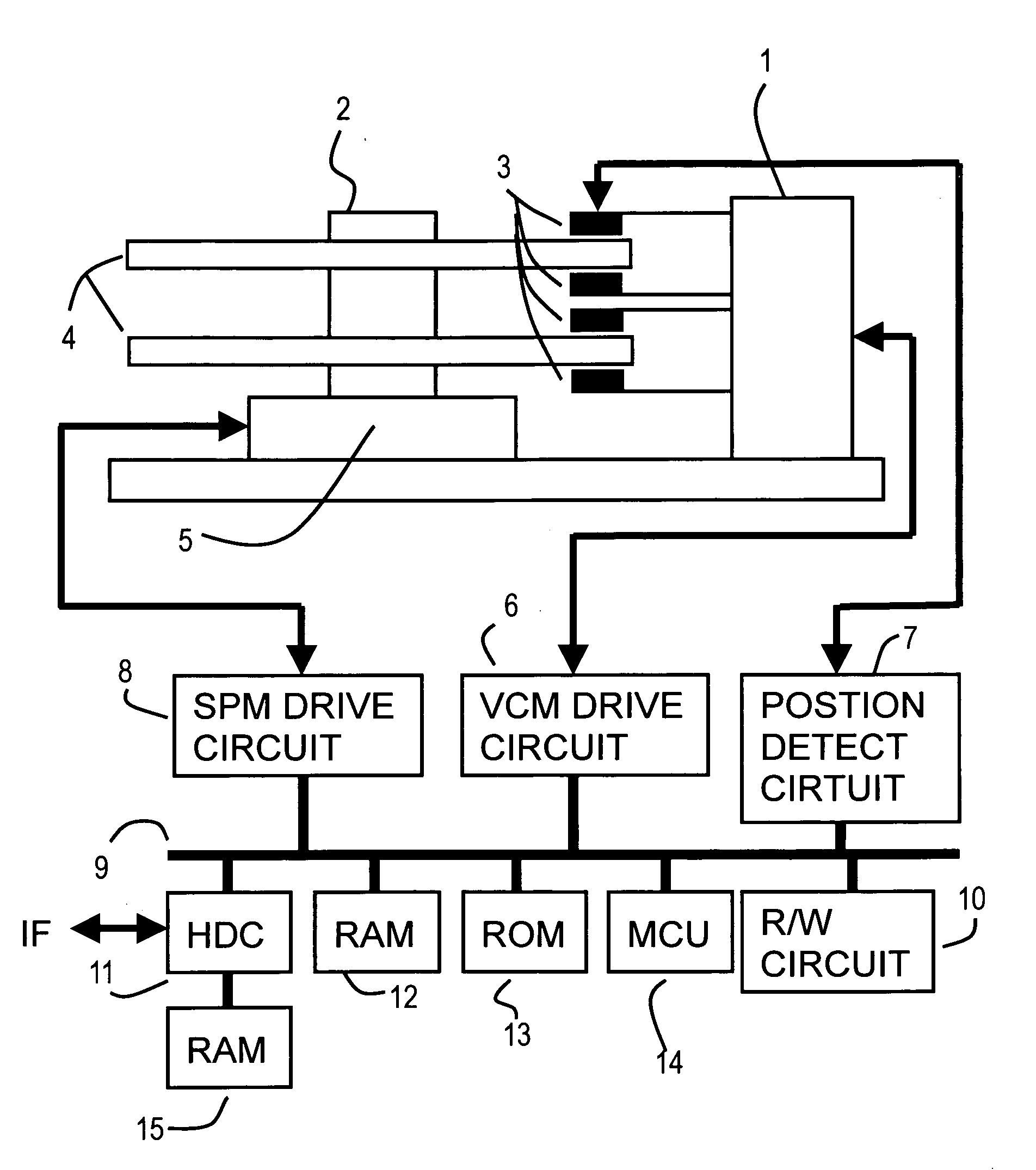
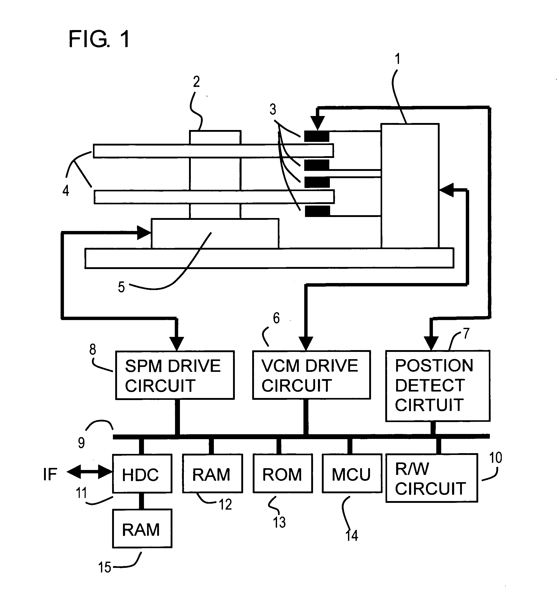
[0073]FIG. 4 is a block diagram depicting a first embodiment of the positioning control system for suppressing the disturbance which is executed by the MCU 14 in FIG. 1. This positioning control system is an observer control system which detects the disturbance frequency and suppresses the disturbance.

[0074]The observer shown in FIG. 4 is a current observer including the bias compensation shown in the following Expressions (1), (2), (3), (4) and (5)

(x(k)v(k)b(k)z1(k)z2(k))=(x(k)v(k)b(k)z1(k)z2(k))+(L1L2L3L4L5)(y(k)-x(k))(1)u(k)=-(F1F2)(x(k)v(k))(2)uout(k)=u(k)-(F3F4F5)(b(k)z1(k)z2(k))(3)(x(k+1)v(k+1))=(1101)(x(k)v(k))+Blm1LpT2(1 / 21)u(k)(4)b(k+1)=b(k)(z1(k+1)z2(k+1))=(a11a12a21a22)(z1(k)z2(k))}(5)

[0075]In other words, this embodiment is an example of a control system where the disturbance model 50 is separated from the model of the controller. In FIG. 4, the first computing block 30 subtracts the target position “r” from the observation positio...

Example

Second Embodiment of Observer

[0142]FIG. 15 is a block diagram depicting the second embodiment of the positioning control section for suppressing the disturbance which is executed by the MCU 14 in FIG. 1.

[0143]This positioning control system is an observer control system which detects the disturbance frequency and suppresses the disturbance by adaptive control, and is an adaptive control system where the disturbance models in FIG. 4 is separated, and a plurality of the disturbance models are provided.

[0144]In FIG. 15, composing elements the same as those in FIG. 4 are denoted with the same reference symbols, and each one of the disturbance models 50-1, . . . , 50-N is comprised of the blocks 51, 52, 54, 56 and 58 of the disturbance adaptive control model shown in FIG. 4.

[0145]Each disturbance model 50-1, . . . , 50-N is set for each disturbance frequency which requires follow up. The output of each disturbance model 50-1, . . . , 50-N is added in the addition block 62, and the result...

Example

Examples of Second Embodiment

[0149]FIG. 16 to FIG. 19 are diagrams depicting the first example of the second embodiment of the present invention, where FIG. 16 is characteristic diagrams of the shaping filter, FIG. 17 is open loop characteristic diagrams, FIG. 18 is a characteristic diagram of the sensitivity function, and FIG. 19 is a characteristic diagram of acceleration disturbance.

[0150]FIG. 16 to FIG. 19 are examples of an NRRO (Non-Repeatable Rotation) filter which suppresses three frequencies in notch form. Suppressing a plurality of frequencies is effective when the suppression width is increased to handle various disturbances.

[0151]To suppress a plurality of frequencies, the reverse characteristics of the notch filter must be inserted to the controller in multiple steps, and adjustment thereof is difficult.

[0152]In the present embodiment, a shaping filter for suppressing three specific frequencies (1000 Hz, 1100 Hz, 1600 Hz) is designed, as shown in FIG. 16. For this shapi...


PUM


Abstract

A positioning control device based on an observer control has a disturbance suppression function to which a disturbance suppression function is added without affecting the control characteristics of the observer. Models of an actuator and a disturbance model are separated, and for the disturbance model, state information is generated using an estimated gain determined from a disturbance model defined by a transfer function of which denominator is a numerator of a filter in which degrees of denominator and numerator for shaping a sensitivity function are the same, and the disturbance suppression value of the actuator is computed from the state information. The vibration of the head can be prevented adapting to a wide range of disturbance frequencies without affecting the control characteristics of the observer.

Description

CROSS-REFERENCE TO RELATED APPLICATIONS[0001]This application is based upon and claims the benefit of priority from the prior Japanese Patent Application No. 2006-125113, filed on Apr. 28, 2006, the entire contents of which are incorporated herein by reference.BACKGROUND OF THE INVENTION[0002]1. Field of the Invention[0003]The present invention relates to a head position control method for a disk device, head position control device and disk device, and more particularly to a head position control method, head position control device and disk device for suppressing position shift by disturbance, using observer control.[0004]2. Description of the Related Art[0005]In a disk device, such as a magnetic disk device and optical disk device, it is extremely important to accurately position the head on the target track to improve recording density.[0006]In this positioning control, it is known that disturbance influences positioning accuracy. To suppress this disturbance by a control system...

Claims


Application Information

Patent Timeline
IPC IPC(8): G05B1/06
CPCG11B5/5547G11B5/59688G11B5/59622G11B5/5582G11B5/596G11B21/10
Inventor TAKAISHI, KAZUHIKO
Owner KK TOSHIBA
Why Eureka
Try Eureka