
Pole mounted illuminated sign

a technology of illuminated signs and poles, which is applied in the direction of lighting support devices, instruments, lighting and heating apparatuses, etc., can solve the problems of difficult vertical adjustment, difficult mounting of conventional register lights, and many steps for mounting register lights, etc., to achieve the effect of convenient mounting and adjustmen

Active Publication Date: 2007-11-01
HUBBELL INC
View PDF16 Cites 29 Cited by
  • Summary
  • Abstract
  • Description
  • Claims
  • Application Information

AI Technical Summary

Benefits of technology

[0006] Accordingly, an object of the present invention is to provide a polygonal lighting unit that is easily mounted and adjusted on a vertical support structure, such as a pole or a multi-outlet assembly.
[0009] A further object of the present invention is to provide a relatively easy to use, cheap to manufacture, and easy to install and adjust lighting unit that indicates to customers what lane is available for checking out.

Problems solved by technology

However, conventional register lights can be difficult to mount directly on the power pole, particularly after the power pole has been installed, and difficult to vertically adjust as desired.
For example, some conventional register lights must be disassembled then reassembled on the power pole, thereby requiring many steps to mount the register light.
This can also result in a less aesthetically pleasing light due to the appearance of multiple parts assembled together.
Also, several additional parts are often required to mount the register light.
Conventional register lights are often difficult to manufacture, expensive to make, and difficult to view from certain angles in a retail establishment.

Method used


Image

  • Pole mounted illuminated sign
  • Pole mounted illuminated sign
  • Pole mounted illuminated sign

Examples


Embodiment Construction

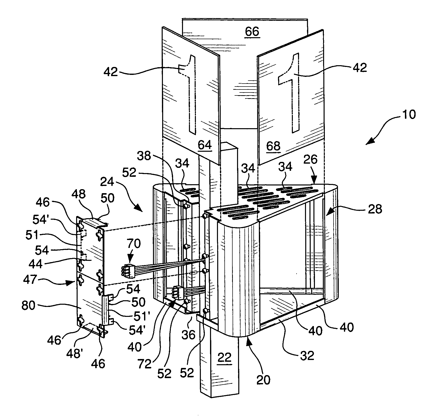
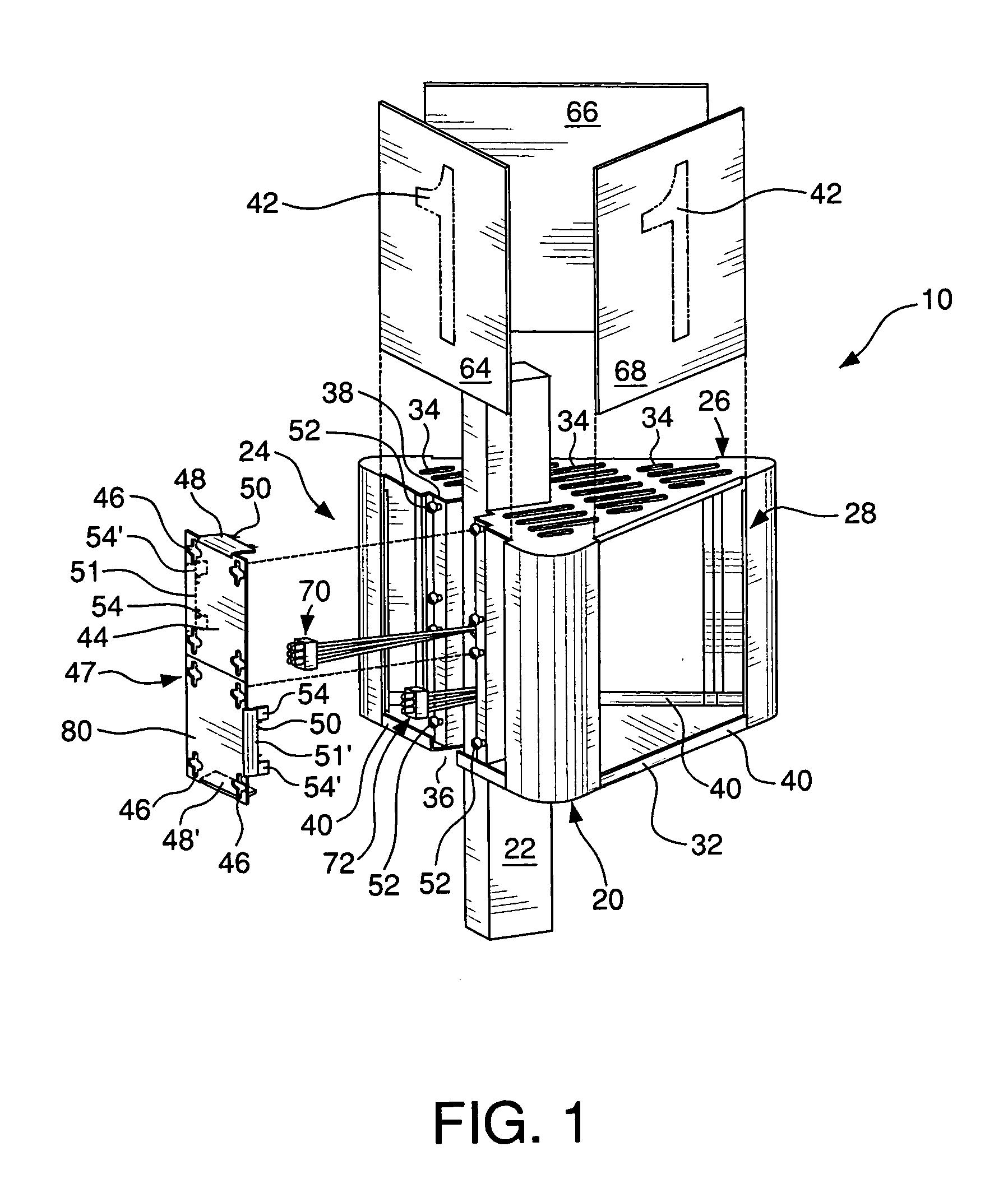
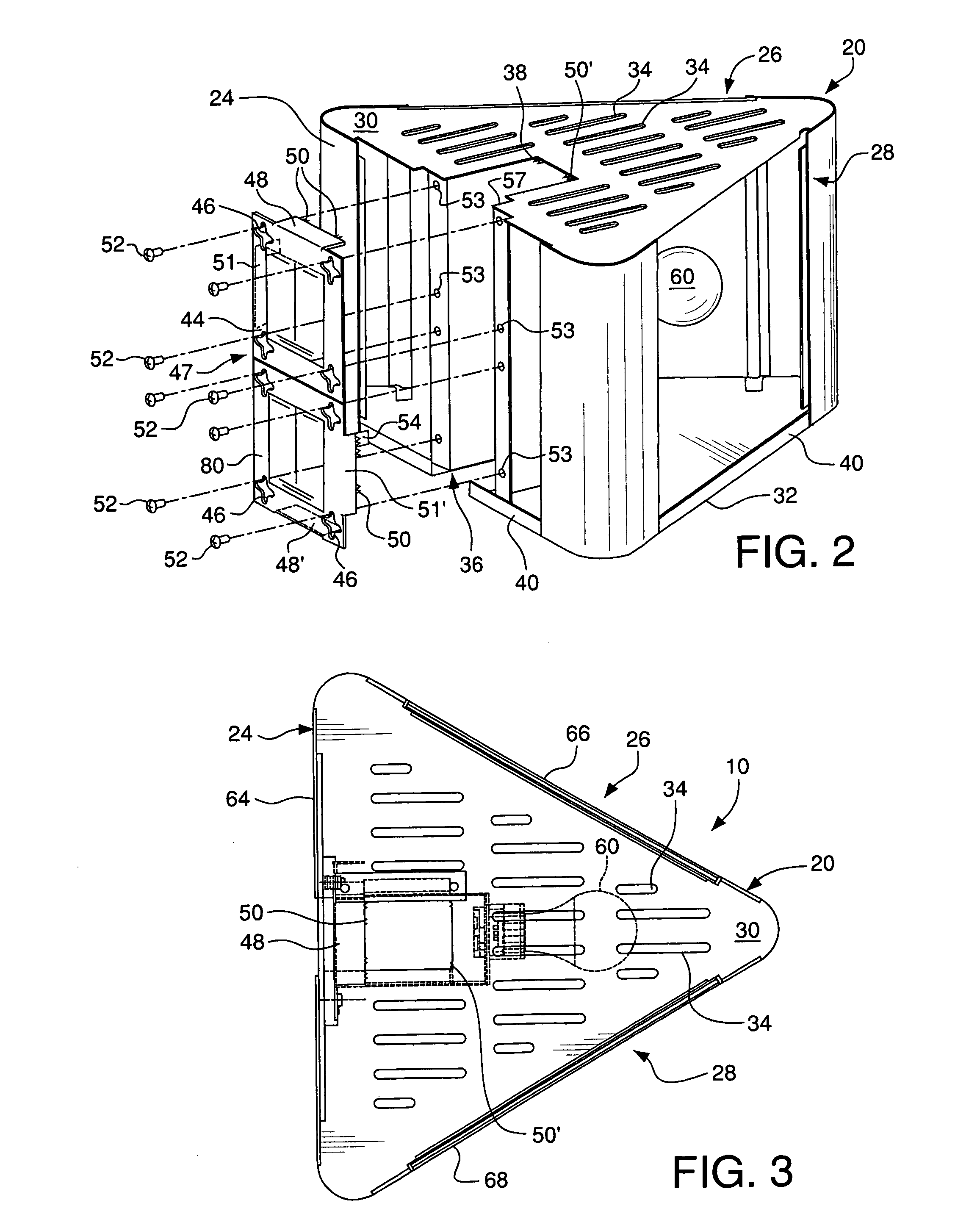
[0023] As seen in FIGS. 1-7, the lighting unit 10 in accordance with an embodiment of the present invention generally includes a substantially polygonal housing 20 adapted to be adjustably mounted to a vertical member, a multi-outlet assembly, or a pole 22. The housing 20 is secured to the pole 22 and further includes at least a first side 24, a second side 26, and a third side 28 with at least one clamp plate 44 engaging the first side 24 and securing the housing 20 to the pole 22.

[0024] Housing 20 of lighting unit 10, as best seen in FIGS. 1 and 5, includes the first side 24, second side 26, and third side 28. Sides 24, 26, and 28 are situated evenly between a top 30 and a base 32 such that the lighting unit 10 can have the same appearance when viewed from a variety of locations. An opening or slot 36 is formed in the first side 24 of the housing 20 with at least one clamp plate 44 engaging the first side 24 and securing the housing 20 to the pole 22. The opening 36 defines a rec...


PUM


Abstract

A lighting unit adapted to be mounted to a vertical member, preferably a pole for use at a checkout counter in a retail service location. The lighting unit includes a substantially polygonal housing secured to the pole. The housing typically includes at least three sides, a top, and a base; the top may have slots to promote ventilation. An opening is formed in the first side of the housing and defines a receiving location for the pole, situated between the top and base of the housing. A clamp plate is releasably engageable with the first side of the housing spans the opening adjacent to the pole, and releasably engages the pole to provide for easy vertical adjustment of the housing relative to the pole. Each flange can advantageously include at least one set of teeth for enhancing the gripping strength of the clamp plates and penetrating the vertical member.

Description

FIELD OF THE INVENTION [0001] The present invention relates to a pole mounted illuminated sign, especially for a commercial retail establishment. More particularly, the present invention relates to an illuminated sign having a housing comprising at least three sides that can receive labeled plaques identifying the housing. The housing further comprises a top for ventilation and a base for support. Still more particularly, the housing is mounted to a vertical pole and an electrical wiring system that provides electricity from the vertical pole to illuminate a lamp inside the housing. A clamp plate is releasably engaged with the side closest to the vertical pole to provide access to the electrical wiring system inside the housing and to allow easy vertical adjustment of the housing relative to the pole. BACKGROUND OF THE INVENTION [0002] Many commercial establishments use light fixtures mounted to a power pole since the pole provides both communication and power wiring, and a convenie...

Claims


Application Information

Patent Timeline
IPC IPC(8): F21S13/10F21V29/00
CPCG09F13/04F21V21/116G09F15/0037Y10S362/812G09F2007/1804G09F13/0445
Inventor HOWARD, CAROL A.MARCONI, DANIEL W.
Owner HUBBELL INC
Learn More