Image coding apparatus and method

Inactive Publication Date: 2007-11-01
CANON KK
View PDF3 Cites 91 Cited by
  • Summary
  • Abstract
  • Description
  • Claims
  • Application Information

AI Technical Summary

Benefits of technology

[0025]The present invention is directed to an image coding apparatus and method that make imag

Problems solved by technology

That is, information about macro-blocks included in another slice cannot be utilized for coding.
As a result, prediction efficiency of intrapicture prediction and interpicture prediction is reduced near the boundary of the slices.
In particular,

Method used


Image

  • Image coding apparatus and method
  • Image coding apparatus and method
  • Image coding apparatus and method

Examples


first exemplary embodiment

[0050]A first exemplary embodiment of the present invention will now herein be described.

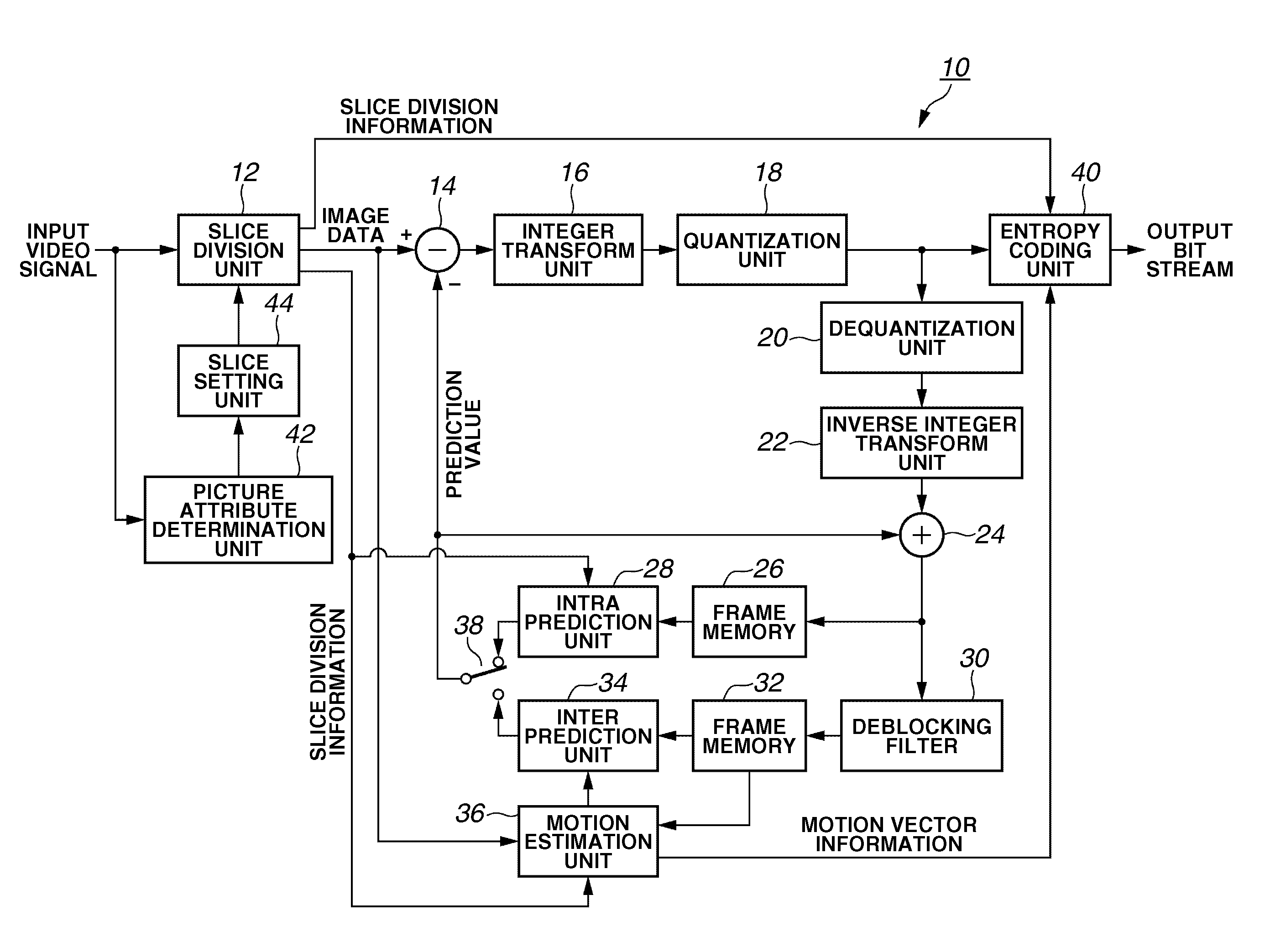
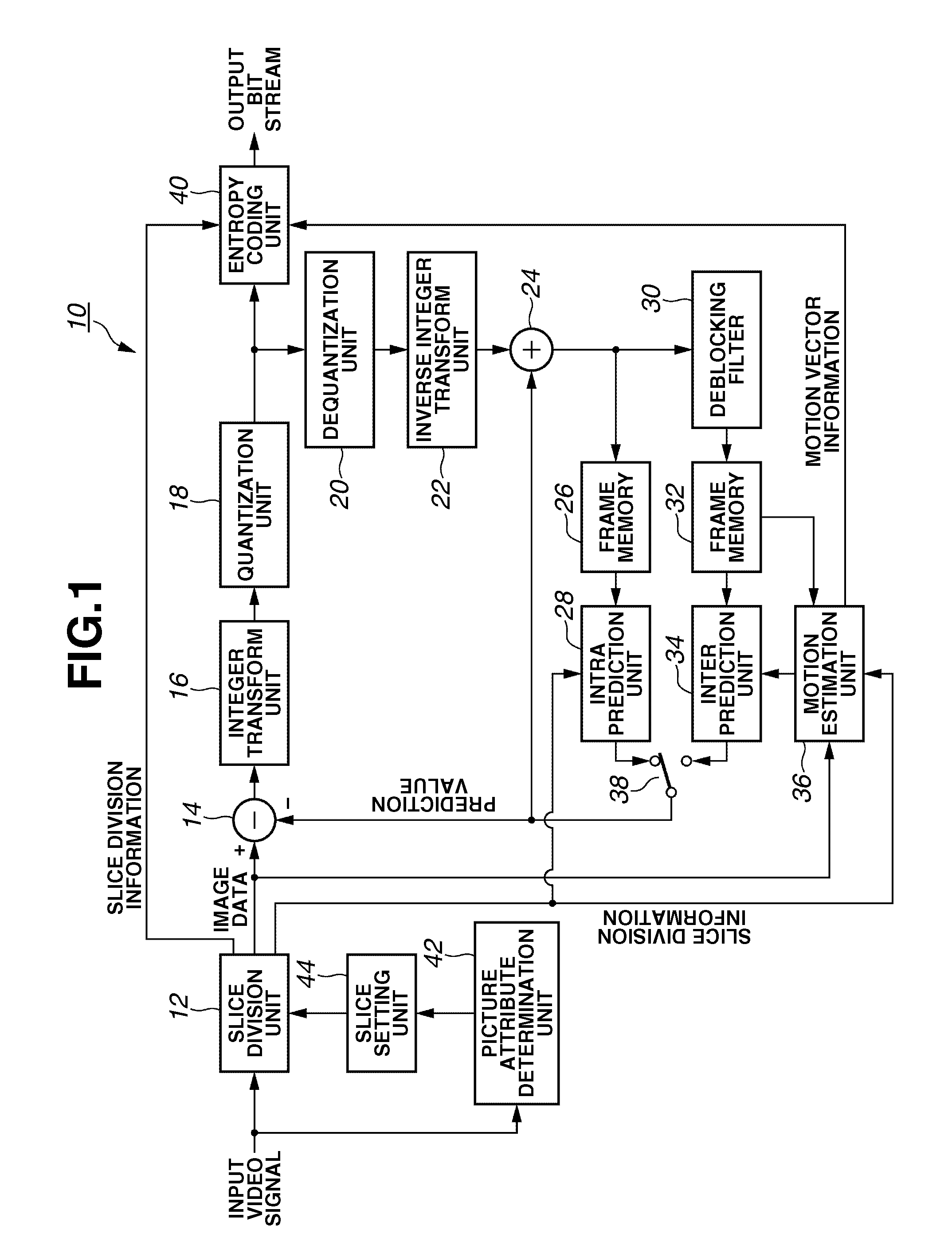
[0051]FIG. 1 illustrates a configuration of an image coding apparatus according to a first exemplary embodiment of the present invention. An image coding apparatus 10 encodes a video signal in compliance with MPEG-4 part-10: AVC (ISO / IEC 14496-10: so-called “H.264”). A video signal input to the image coding apparatus 10 is digital data digitized at a predetermined sampling rate. The image coding apparatus 10 can be applied to a digital video camera and a digital video recorder.

[0052]A picture attribute determination unit 42 determines an attribute of each picture included in the input video signal. That is, the picture attribute determination unit 42 determines whether each picture should be coded into an I picture, a P picture, or a B picture. In performing slice division, the picture attribute determination unit 42 determines an attribute of each slice.

[0053]A slice setting unit 44 determines ...

second exemplary embodiment

[0081]In the first exemplary embodiment, the number of divided slices and the division position are regularly changed according to the picture attribute. In a second exemplary embodiment, the number of divided slices and the division position are changed in the order of picture number (namely, a frame number). FIG. 4 illustrates a configuration of an image coding apparatus according to the second exemplary embodiment. The portions and units similar to those illustrated in FIG. 1 are provided with the same numerals and symbols, and the description thereof is not repeated here.

[0082]An image coding apparatus 10a illustrated in FIG. 4 includes a slice setting unit 46. The slice setting unit 46 counts the number of frames in the input video signal. The slice setting unit 46, according to the counted value, sets a slice division condition to the slice division unit 12 as described below.

[0083]For example, in the case where the three types of slice division method are used, a picture numb...

third exemplary embodiment

[0091]In a third exemplary embodiment, the number of division into slices and the division position can be changed by a method different from the second exemplary embodiment, under a predetermined rule. In the description of the third exemplary embodiment, the block diagram in FIG. 4 is used to illustrate a configuration of an image coding apparatus according to the third exemplary embodiment.

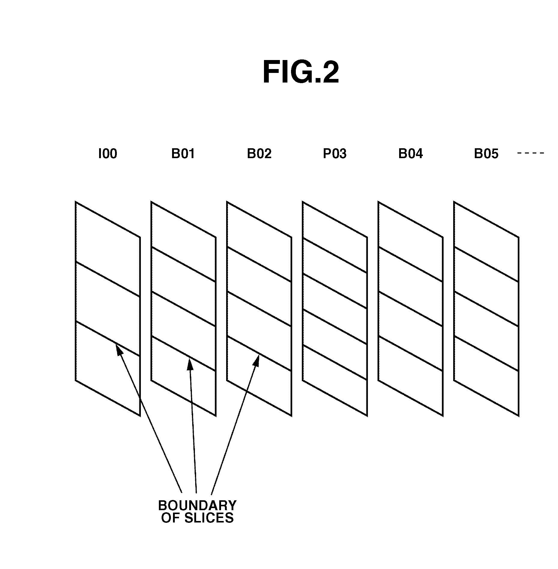
[0092]In FIG. 7, consecutive pictures (00, 01, 02, 03, 04, 05 . . . ) are divided into slices at different boundary positions according to picture numbers thereof. FIG. 8 illustrates the slice division positions in a cross section of each picture in FIG. 7.

[0093]Referring to FIG. 8, unfilled circles, filled circles, filled triangles, and filled rectangles indicate slice division positions. An auxiliary line A represents a change of the slice division position indicated with filled circle, with respect to a group of pictures whose numbers are exactly divisible by 3 (I00, P03, P06, P09 . . . ) (f...


PUM


Abstract

An image coding apparatus includes: a division unit configured to divide a coding target picture included in an input video signal into a plurality of slices each including one or more data blocks; a coding unit configured to code the video signal in a unit of the slice divided by the division unit; and a setting unit configured to set at least one of a division position of the slice and a number of divisions of the slice, to the division unit. In the image coding apparatus, the setting unit sets at least one of the division position of the slice and the number of divisions of the slice so that slice boundaries differ from each other between adjacent pictures.

Description

BACKGROUND OF THE INVENTION[0001]1. Field of the Invention[0002]The present invention relates to an image coding apparatus and a method for compression-coding a vide signal. More specifically, the present invention relates to an apparatus and a method for coding a video signal by slice dividing.[0003]2. Description of the Related Art[0004]As a highly efficient compression-coding method for transmitting or accumulating image information, Moving Picture Experts Group (MPEG)-2 and MPEG-4 are known. In addition, MPEG-4 Part-10: AVC (ISO / IEC 14496-10 “Part-10 Advanced Video Coding”) is proposed, that is also named H.264. These compression methods achieve a high compression rate utilizing an orthogonal transform such as a discrete cosine transform (DCT), a motion compensation, and inter-picture and intra-picture redundancy.[0005]In H.264, pictures to be coded are classified as an I picture, a P picture, and a B picture, according to a difference in a method of prediction. Each picture inc...

Claims


Application Information

Patent Timeline
IPC IPC(8): H04N11/04H04N7/12H04N19/50H04N19/13H04N19/159H04N19/503H04N19/577H04N19/61H04N19/625H04N19/86H04N19/91
CPCH04N19/00072H04N19/119H04N19/174H04N19/114H04N19/61
Inventor MAKINO, JUN
Owner CANON KK
Why Eureka
Try Eureka