
Method and system for fully fixed vehicle control surfaces
a vehicle control surface and fully fixed technology, applied in the direction of airflow influencers, drag reduction, wings, etc., can solve the problems of inefficient structural structure of the flap surface, complex mechanical flap surface actuation system, heavy hydraulic or electric actuation system, etc., to achieve efficient and efficient actuation, the effect of reducing drag
- Summary
- Abstract
- Description
- Claims
- Application Information
AI Technical Summary
Benefits of technology
Problems solved by technology
Method used
Image

Examples
Embodiment Construction
[0026]Preferred embodiments of the present invention are illustrated in the figures like numerals being used to refer to like and corresponding parts of the various drawings.
[0027]The present invention provides a fully fixed, non-articulating geometry vehicle that substantially eliminates or reduces disadvantages and problems associated with previous designs.
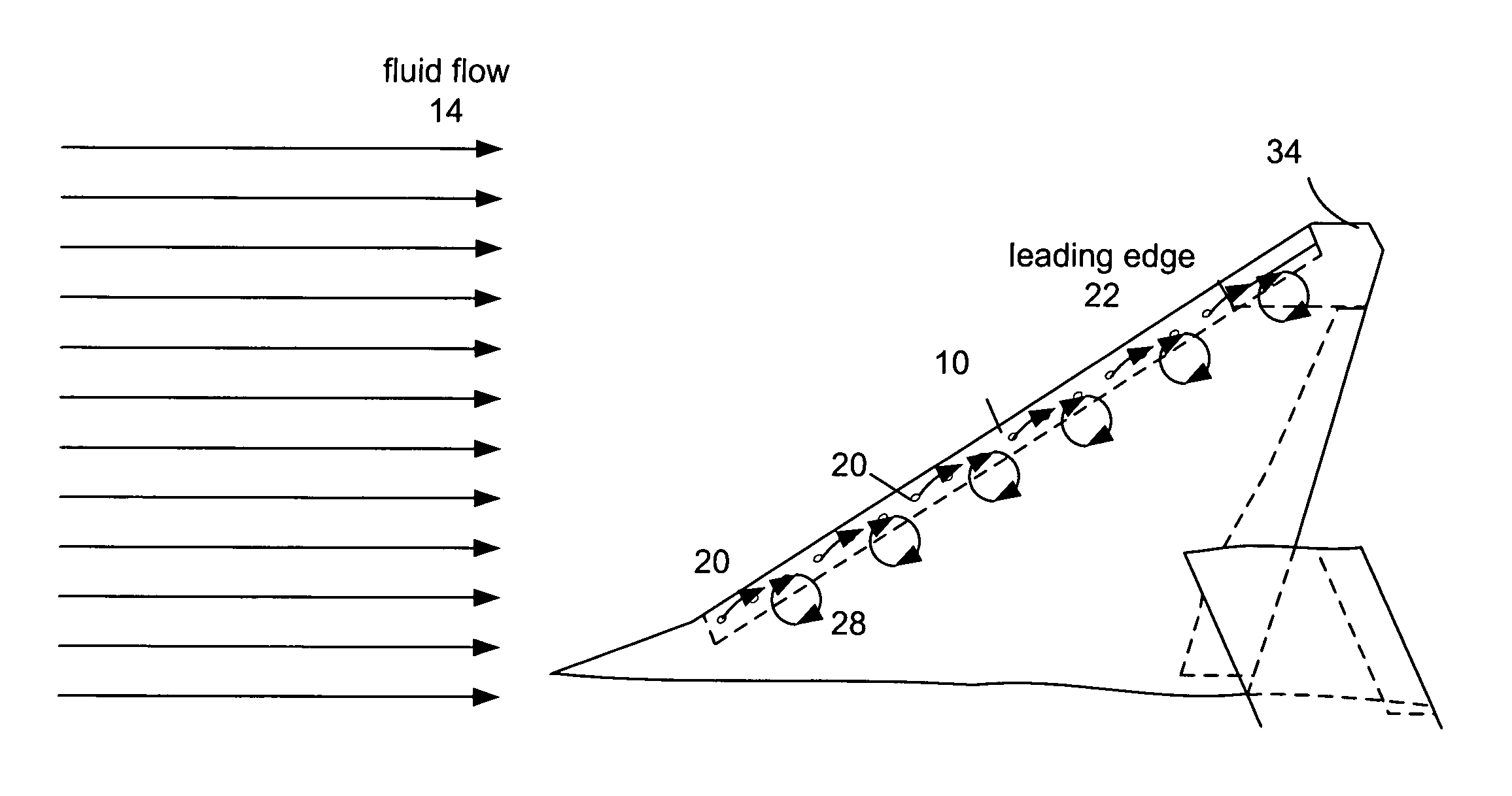
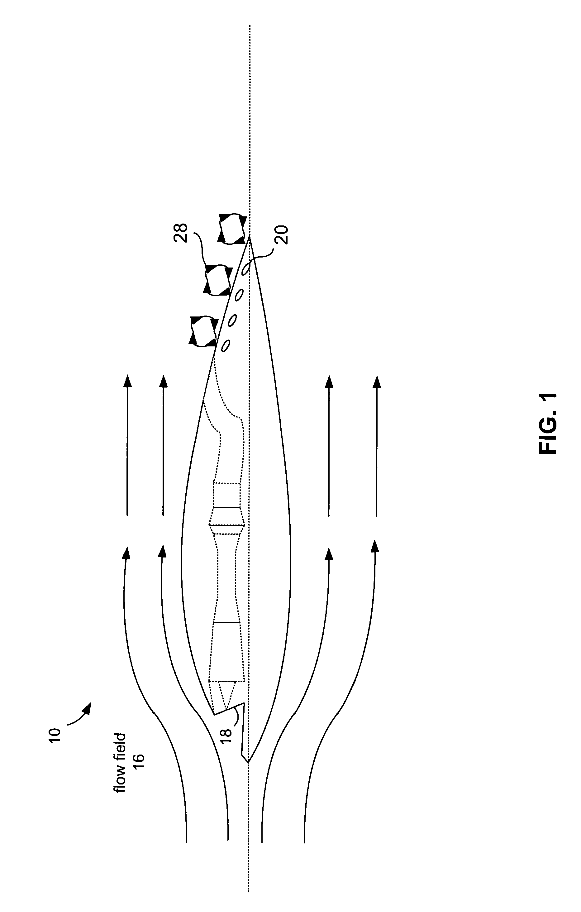
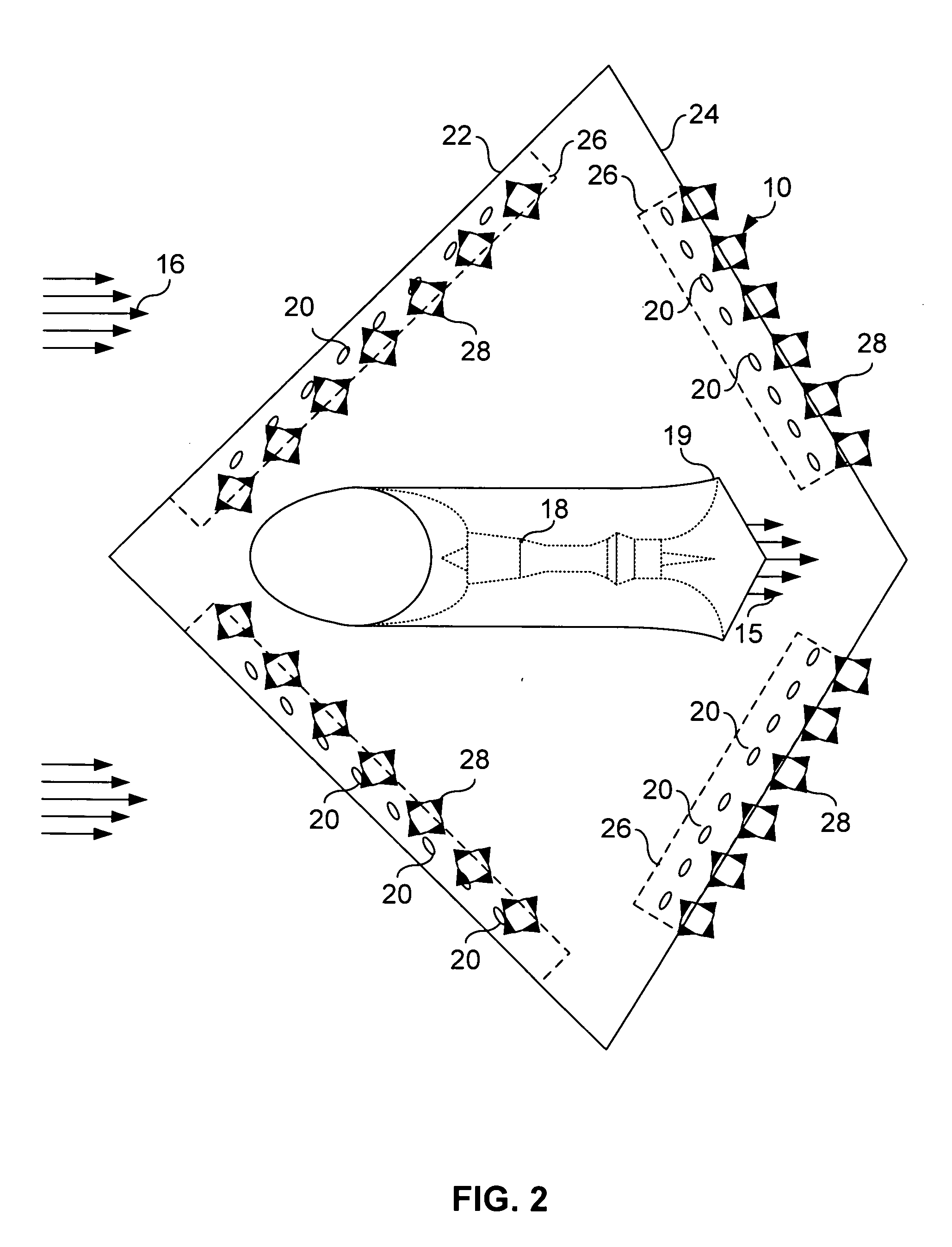
[0028]FIG. 1 provides a cross sectional view of a fully fixed, non-articulating geometry vehicle such as aircraft 10. FIG. 2 provides a top-down view of aircraft 10. Aircraft 10 may be a blended wing body (BWB) aircraft wherein engine 18 is submerged within the BWB of aircraft 10. Distributed arrays of flow control devices 20 submerged in the boundary layer along the leading edge 22 and trailing edge 24 help create or define virtual control surfaces 26 by inducing secondary flow structures 28.
[0029]Flow control devices 20 may include arrays of small scale positive displacement sub-boundary layer vanes (i.e. micro vanes) and / or c...
PUM
 Abstract
Description
Claims
Application Information