Gas-transfer foot

a technology of gas transfer foot and gas transferring rod, which is applied in the direction of machines/engines, transportation and packaging, liquid fuel engines, etc., can solve the problem of low-pressure area behind

Inactive Publication Date: 2007-11-01
COOPER PAUL
View PDF2 Cites 93 Cited by
  • Summary
  • Abstract
  • Description
  • Claims
  • Application Information

AI Technical Summary

Problems solved by technology

One problem with releasing gas into a metal-transfer conduit is that, in some systems, the conduit (called a gas-transfer conduit) that transfers the gas from a gas source into the molten metal stream typically extends into the metal-transfer conduit, usually extending downward from the top of the metal-transfer conduit, and disrupts the flow of molten metal passing through the conduit and creating a low-pressure area behind the portion of the gas-transfer conduit extending into the metal-transfer conduit.
The low-pressure area can interfere with the released gas mixing with molten metal passing through the metal-transfer conduit because, among other things, the gas immediately rises into the low-pressure area instead of mixing with molten metal throughout the metal-transfer conduit.

Method used


Image

  • Gas-transfer foot
  • Gas-transfer foot
  • Gas-transfer foot

Examples


Embodiment Construction

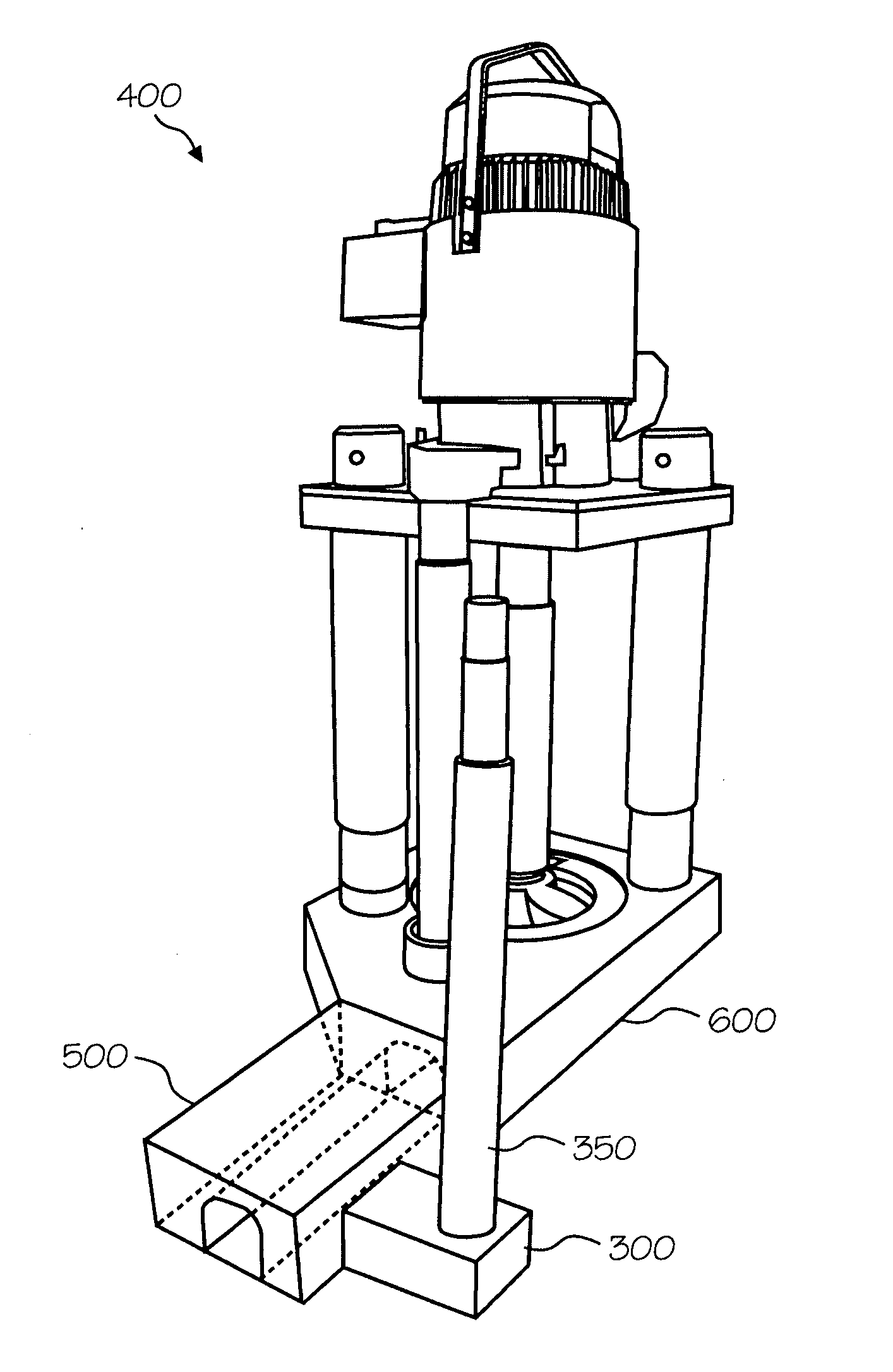
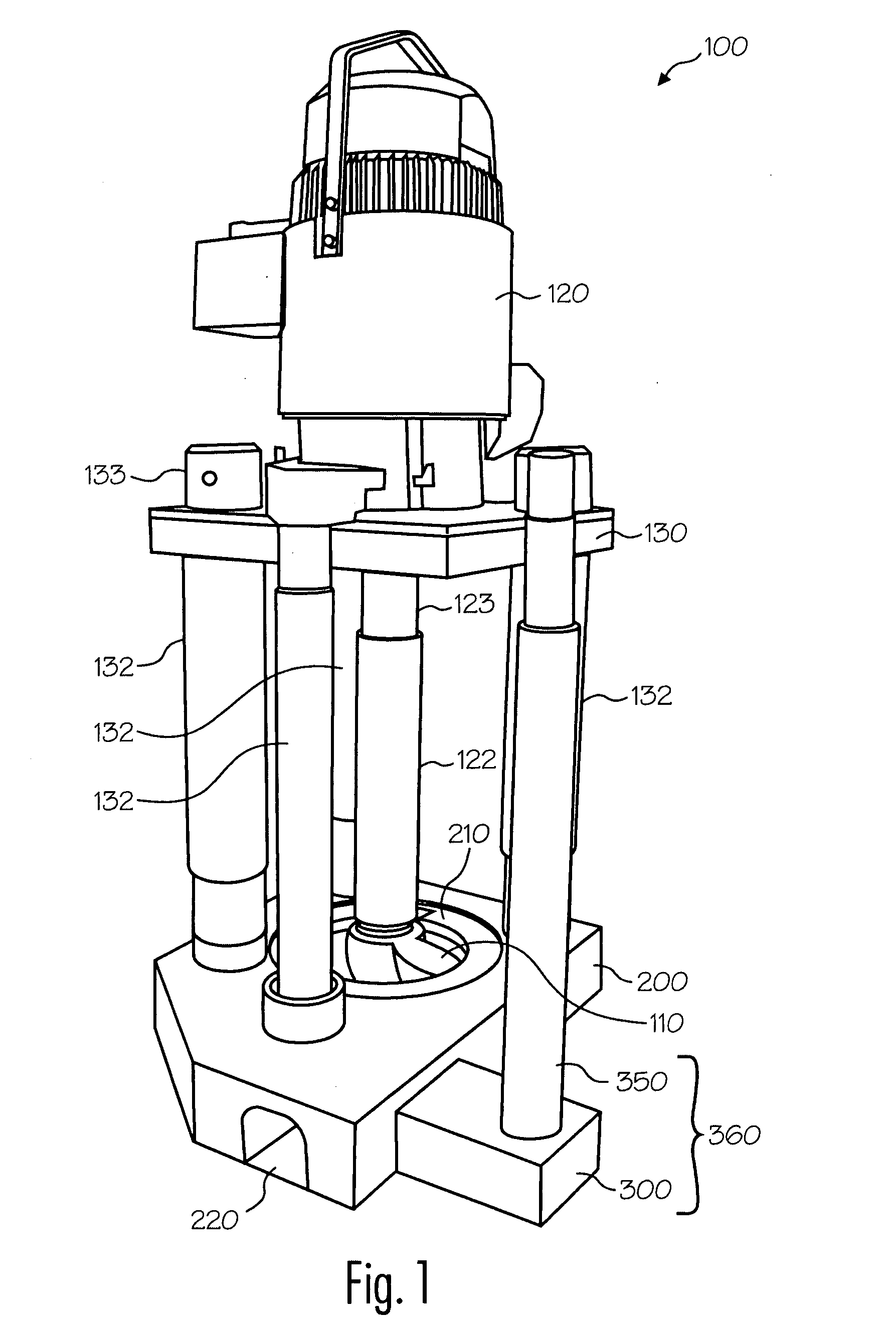
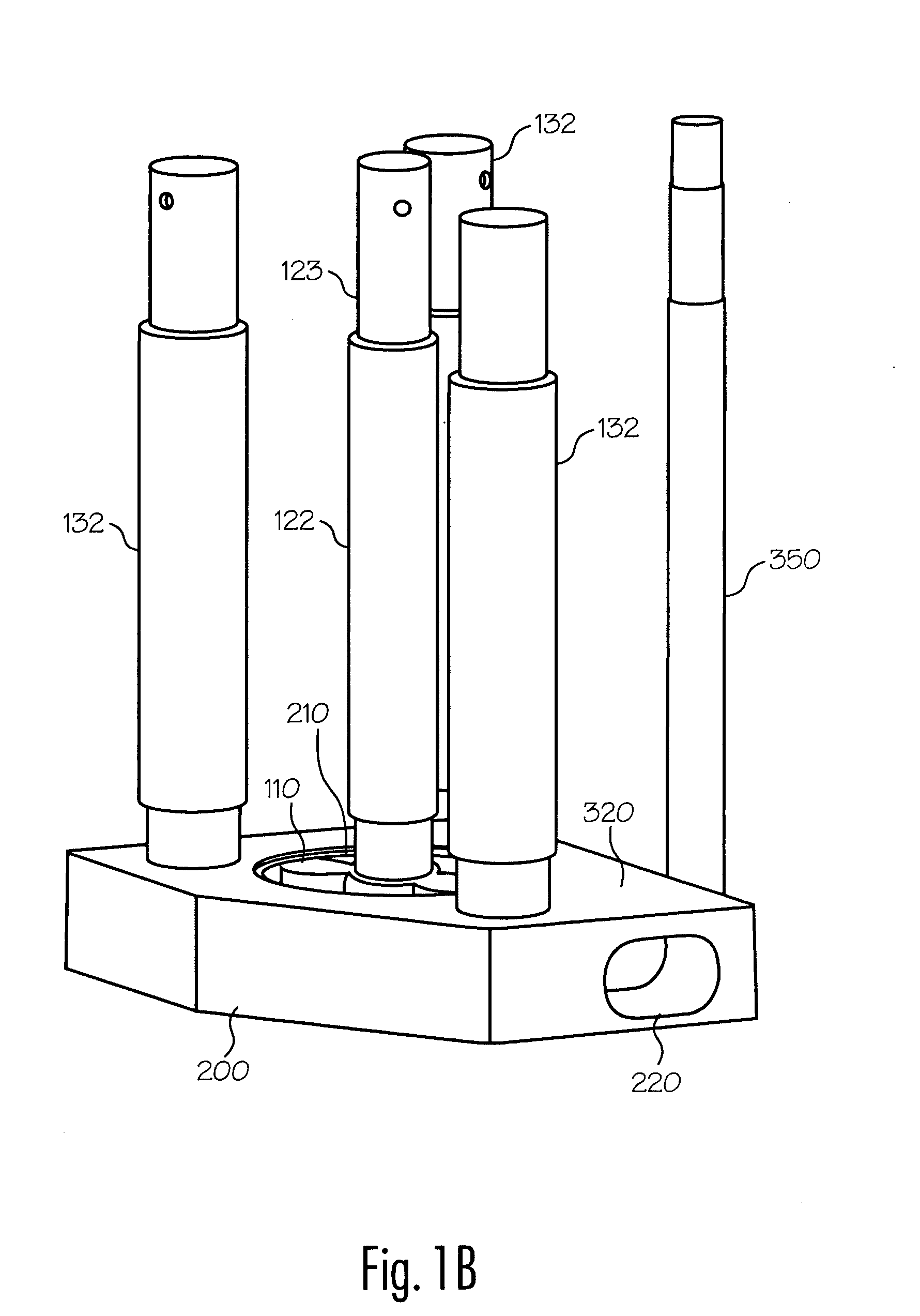
[0039] Reference will now be made in detail to the present exemplary embodiments of the invention, examples of which are illustrated in the accompanying drawings. FIG. 1A depicts a molten metal pump 100 according to the invention. When in operation, pump 100 is typically positioned in a molten metal bath in a pump well, which is typically part of the open well of a reverbatory furnace. Pump 100 includes motor 120, superstructure 130, support posts 132, drive shaft 122, rotor 110, base 200, gas-transfer foot 300 and gas-transfer tube 350.

[0040] The components of pump 100 that are exposed to the molten metal (such as support posts 132, drive shaft 122, rotor 110, base 200, gas-transfer foot 300 and gas-transfer tube 350) are preferably formed of structural refractory materials, which are resistant to degradation in the molten metal. Carbonaceous refractory materials, such as carbon of a dense or structural type, including graphite, graphitized carbon, clay-bonded graphite, carbon-bon...


PUM


Abstract

The present invention includes a molten metal pump and associated components that enable gas to be released into a stream of molten metal. The gas may be released into the molten metal stream (preferably into the bottom of the stream) flowing through a passage. Such a stream may be within the pump discharge and/or within a metal-transfer conduit extending from the pump discharge. The gas is released by using a gas-transfer foot that is positioned next to and is preferably attachable to the pump base or to the metal-transfer conduit. Preferably, the conduit (and/or discharge) in which the gas is released comprises two sections: a first section having a first cross-sectional area and a second section downstream of the first section and having a second cross-sectional area, wherein the second cross sectional area is larger than the first cross-sectional area. Preferably, the gas is released into or near the second section so that the gas is released into an area of relatively lower pressure.

Description

FIELD OF THE INVENTION [0001] The invention relates to releasing gas into molten metal and more particularly, to a device for releasing gas into the bottom of a stream of molten metal that may utilize the flow of the molten metal stream to assist in drawing the gas into the stream. In this manner, the gas may be more effectively mixed into the molten metal. BACKGROUND OF THE INVENTION [0002] As used herein, the term “molten metal” means any metal or combination of metals in liquid form, such as aluminum, copper, iron, zinc and alloys thereof. The term “gas” means any gas or combinations of gases, including argon, nitrogen, chlorine, fluorine, Freon, and helium, which are released into molten metal. [0003] Known pumps for pumping molten metal (also called “molten metal pumps”) include a pump base (also called a housing or casing), one or more inlets, an inlet being an opening to allow molten metal to enter a pump chamber (and is usually an opening in the pump base that communicates w...

Claims


Application Information

Patent Timeline
Patent Type & Authority Applications(United States)
IPC IPC(8): F01D1/36
CPCF04D7/065F04D7/00F04D31/00F04D29/708F17D1/04Y10T137/85978
Inventor COOPER, PAUL
Owner COOPER PAUL
Why Eureka
Try Eureka