Infusion device with active and passive check valves

a check valve and infusion device technology, applied in the field of medical devices, can solve the problems of affecting the precise delivery of substances, affecting the delivery of substances, etc., and achieve the effect of increasing the energy required

Active Publication Date: 2007-11-01
MEDTRONIC INC
View PDF23 Cites 50 Cited by
  • Summary
  • Abstract
  • Description
  • Claims
  • Application Information

AI Technical Summary

Benefits of technology

[0009] The present invention provides an infusion system in which therapeutic substance from a reservoir is pumped by a bolus pump to an infusion port. The therapeutic substance delivered by the bolus pump passes first through a passive check valve located downstream from the pump. The passive check valve opens in response to fluid pressure of the therapeutic substance. After passing through the passive check valve, the therapeutic substance passes through an active check valve located downstream from the passive check if the active check valve is actuated such that it is open. When not activated, the active check valve is closed and fluid flow through the active check valve in the downstream direction is prevented.
[0010] The use of an active check valve located in the fluid pathway downstream of the pump may enhance energy efficiency in an infusion device by reducing flow resistance for therapeutic substance as compared to infusion devices in which therapeutic substance must be forced through normally closed passive check valves. Flow resistance may preferably be reduced because the active check valve does not rely on fluid pressure exerted on the valve using the pump to open a valve. For example, if the active check valve is in the form of a solenoid check valve, one or more coils may be energized to open the check valve. It may be preferred that the opening occur slightly before or at the same time as a pumping event.
[0011] In some embodiments incorporating a normally closed active check valve downstream from a pump as described herein, the likelihood of excess substance infusion due to inadvertent over-pressurization of the device reservoir may be substantially reduced or eliminated. This protection may be afforded without the introduction of potential flow interruptions downstream that would be provided using, e.g., a forward-opening check valve with a high cracking pressure. As a result, the active check valves may prevent flow when needed, yet limit interference with fluid flow during normal device operation. Still further, some active check valves as described herein as “back-closing” may correspondingly increase sealing pressure as reservoir pressure elevates (and / or ambient pressure decreases), improving substance containment even at relatively high differential pressures.
[0012] The combination of a passive check valve arranged to allow flow in the downstream direction and prevent flow in the upstream direction provided in series with an active check valve provided downstream of the passive check valve to allow flow in the downstream direction when activated, but prevent flow in the downstream direction when closed may provide an infusion device in which energy efficiency and safety may be improved.
[0015] In one aspect, the present invention provides an implantable therapeutic substance infusion device that includes a therapeutic substance reservoir; control electronics operably connected to a power source; a bolus pump operably connected to the power source and the control electronics, the bolus pump further operably connected to the reservoir and configured to pump a therapeutic substance from the therapeutic substance reservoir in a downstream direction from the bolus pump to an infusion port in response to a pump signal received from the control electronics; a passive check valve located in a fluid pathway between the infusion port and the bolus pump, the passive check valve comprising a normally closed valve that opens in response to fluidic pressure generated by operation of the bolus pump; and an active check valve located in the fluid pathway between the passive check valve and the infusion port, wherein the active check valve comprises a normally closed valve that opens in response to an open signal from the control electronics, and wherein fluid flow in the downstream direction through the active check valve is prevented when the active check valve is closed.
[0016] In another aspect, the present invention provides an implantable therapeutic substance infusion device that includes a therapeutic substance reservoir; control electronics operably connected to a power source; a bolus pump operably connected to the power source and the control electronics, the bolus pump further operably connected to the reservoir and configured to pump a therapeutic substance from the therapeutic substance reservoir in a downstream direction from the bolus pump to an infusion port in response to a pump signal received from the control electronics; a passive check valve located in a fluid pathway between the infusion port and the bolus pump, the passive check valve comprising a normally closed valve that opens in response to fluidic pressure generated by operation of the bolus pump; a solenoid check valve located in the fluid pathway between the passive check valve and the infusion port, the solenoid check valve comprising a normally closed valve that opens in response to an open signal from the control electronics, wherein fluid flow in the downstream direction through the solenoid check valve is prevented when the solenoid check valve is closed, and wherein fluid pressure on an upstream side of the solenoid check valve increases the energy required to open the solenoid check valve; and an implantable biocompatible housing, wherein the power source, control electronics, bolus pump, passive check valve, and solenoid check valve are contained within the housing.

Problems solved by technology

Yet, various factors may adversely impact precise substance delivery.
With such devices, the application of an external force may compress the reservoir and thus elevate reservoir pressure.
The pump, seals, and other components downstream of the reservoir may then be exposed to this elevated pressure, potentially resulting in excess substance infusion and / or component (e.g., pump) damage.

Method used


Image

  • Infusion device with active and passive check valves
  • Infusion device with active and passive check valves
  • Infusion device with active and passive check valves

Examples


Embodiment Construction

[0025] In the following detailed description of illustrative embodiments of the invention, reference is made to the accompanying figures of the drawing which form a part hereof, and in which are shown, by way of illustration, specific embodiments in which the invention may be practiced. It is to be understood that other embodiments may be utilized and structural changes may be made without departing from the scope of the present invention.

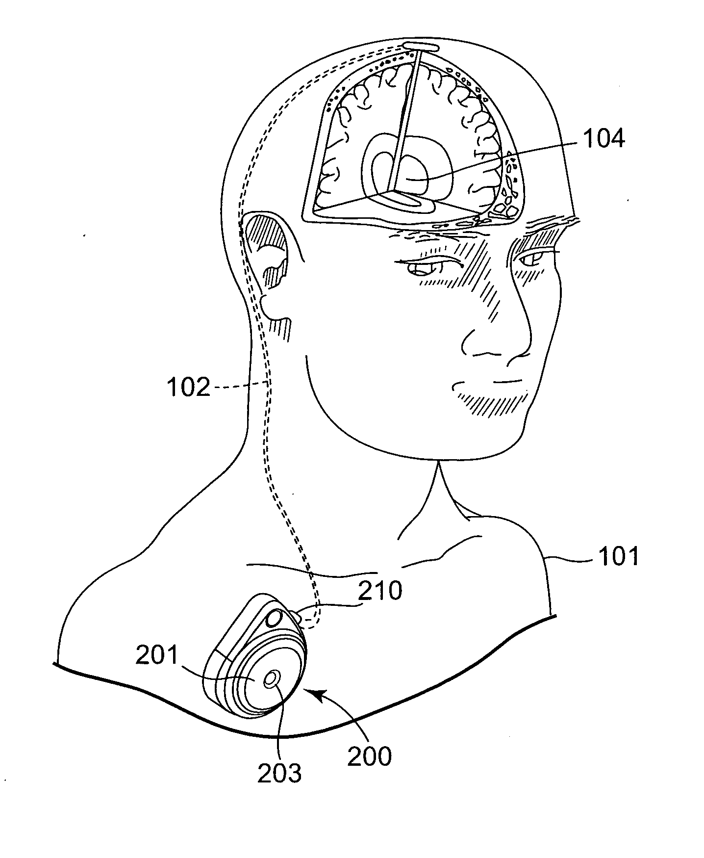
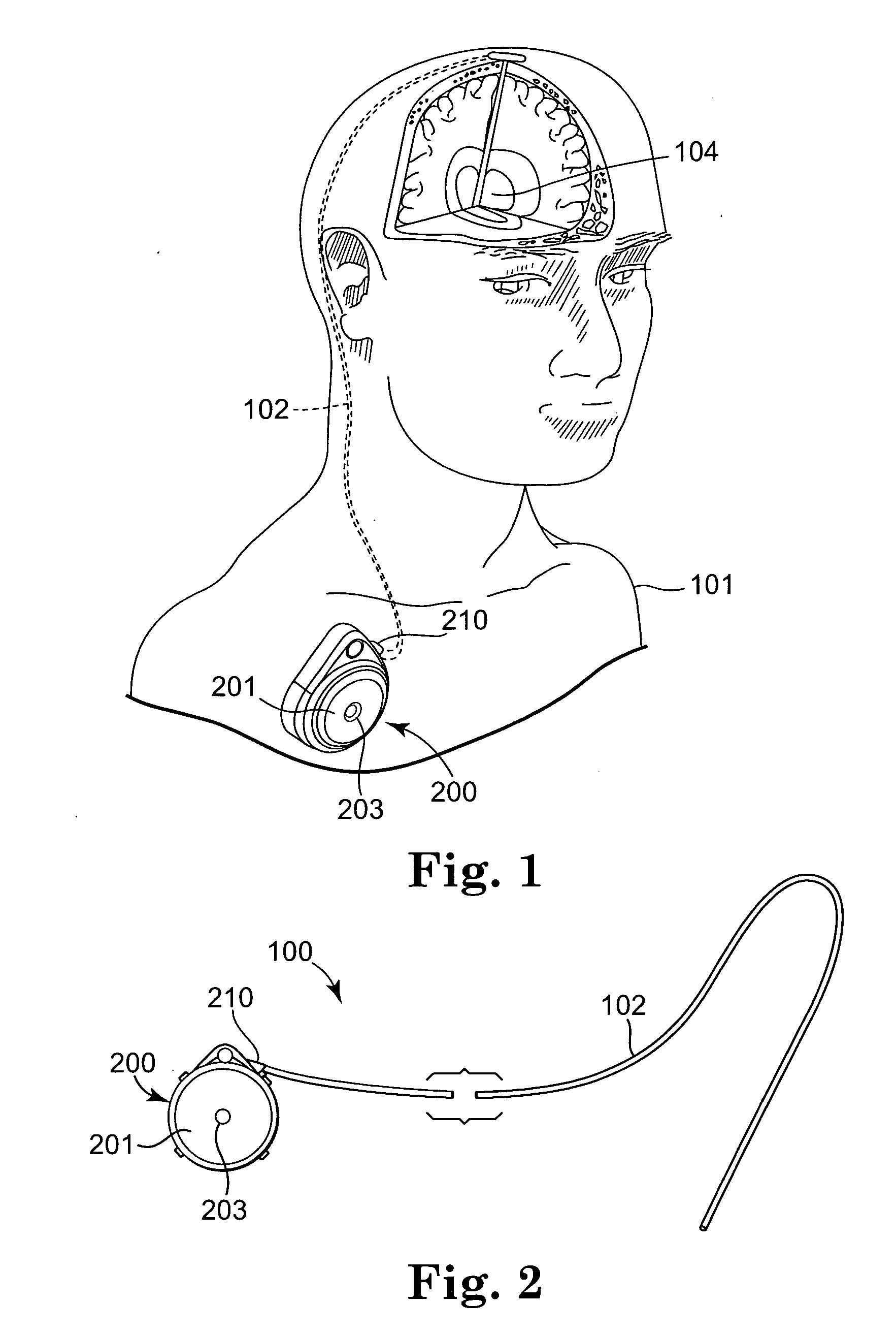
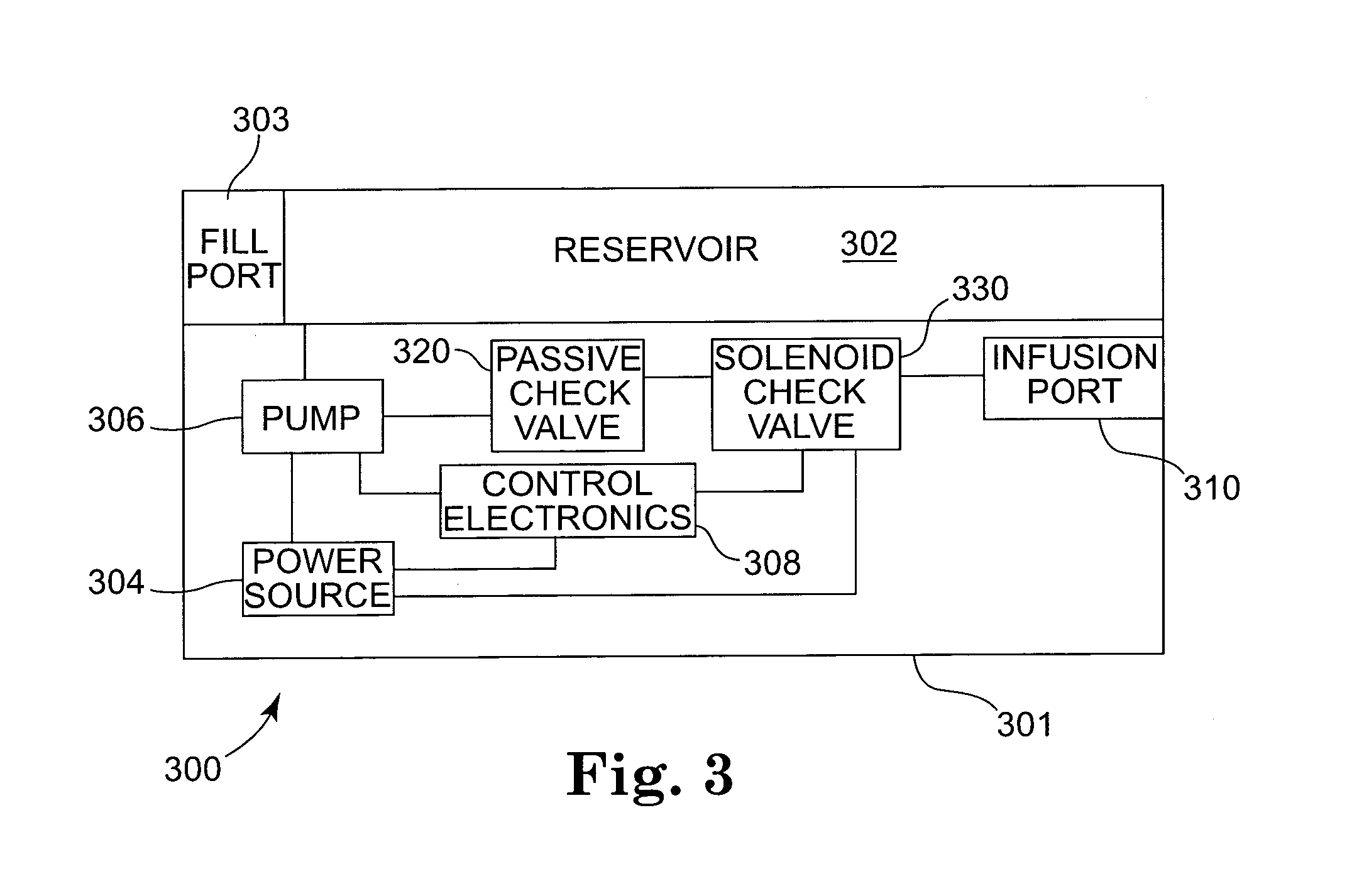
[0026] The present invention is directed to medical devices and, in particular, to infusion devices and systems that are implanted within a patient's body. Infusion devices in accordance with embodiments of the present invention typically incorporate a pair of check valves including a normally closed passive check valve and an active check valve provided in series downstream from a pump mechanism.

[0027] A “passive check valve” as used in connection with the present invention refers to a normally closed check valve that moves from its normally clo...


PUM


Abstract

An infusion system in which therapeutic substance from a reservoir is pumped by a bolus pump to an infusion port is disclosed. The therapeutic substance delivered by the bolus pump passes first through a passive check valve located downstream from the pump. The passive check valve opens in response to fluid pressure of the therapeutic substance. After passing through the passive check valve, the therapeutic substance passes through an active check valve located downstream from the passive check if the active check valve is actuated such that it is open. When not activated, the active check valve is closed and fluid flow through the active check valve in the downstream direction is prevented.

Description

TECHNICAL FIELD [0001] The present invention relates generally to a medical device and, more particularly, to an implantable infusion device including a bolus pump delivering a therapeutic substance through a passive check valve and an active check valve. BACKGROUND [0002] Treatment of diseases and ailments of the body often benefit from short—or long-term infusion of drugs and / or other fluids. While such therapeutic substances may be administered extracorporally, e.g., via transcutaneous injection, many patient benefit from the consistent and repeatable dosage provided by an implantable infusion pump. Such pumps may be used in a variety of applications such as control of pain and / or spasticity. They are well-suited to deliver infusate fluids to a targeted delivery site such as an epidural or intrathecal space of the spinal canal, or a particular location within the brain. [0003] Implantable infusion pumps are typically implanted subcutaneously, e.g., in the chest or abdominal cavit...

Claims


Application Information

Patent Timeline
Patent Type & Authority Applications(United States)
IPC IPC(8): A61M5/00A61M31/00A61K9/22
CPCA61M5/14216A61M5/14276A61M5/16881A61M2039/248A61M2039/242A61M2039/2473A61M39/24
Inventor HAASE, JAMES MARTIN
Owner MEDTRONIC INC
Why Eureka
Try Eureka