
Measuring system and method for the functional monitoring thereof

a measuring system and functional monitoring technology, applied in the field of measuring systems, can solve the problems of significant effect on the cost of a measuring system, no longer be able to compare, and reduce the outlay of wiring, so as to achieve the effect of safe and reliable operation of processing machines and relatively low outlay for signal transmission

Inactive Publication Date: 2007-11-01
DR JOHANNES HEIDENHAIN GMBH
View PDF10 Cites 0 Cited by
  • Summary
  • Abstract
  • Description
  • Claims
  • Application Information

AI Technical Summary

Benefits of technology

[0012] According to an example embodiment of the present invention, a measuring system is provided which may render possible a safe and reliable operation of processing machines, the outlay for signal transmission being comparatively low.
[0013] Moreover, according to an example embodiment of the present invention, a method for checking error information may significantly enhance the safety and reliability of processing machines.

Problems solved by technology

This may reduce the outlay for wiring, which may have a significant effect on the costs of a measuring system.
However, since analog position signals may be missing in the machine control, it may no longer be possible for this comparison to be made.
This manner of transmitting error information may be disadvantageous, e.g., in the case of safety-related monitoring, because it may not be ruled out that a defect may cause a constant level of an error bit to continually be output, thus that this defect does not permit a change in level even in the case of faults or malfunctions.
However, the performance reliability of the monitoring electronics itself may not be checked.
Moreover, the outlay entailed for signal transmission may be comparatively large.

Method used


Image

  • Measuring system and method for the functional monitoring thereof
  • Measuring system and method for the functional monitoring thereof
  • Measuring system and method for the functional monitoring thereof

Examples


Embodiment Construction

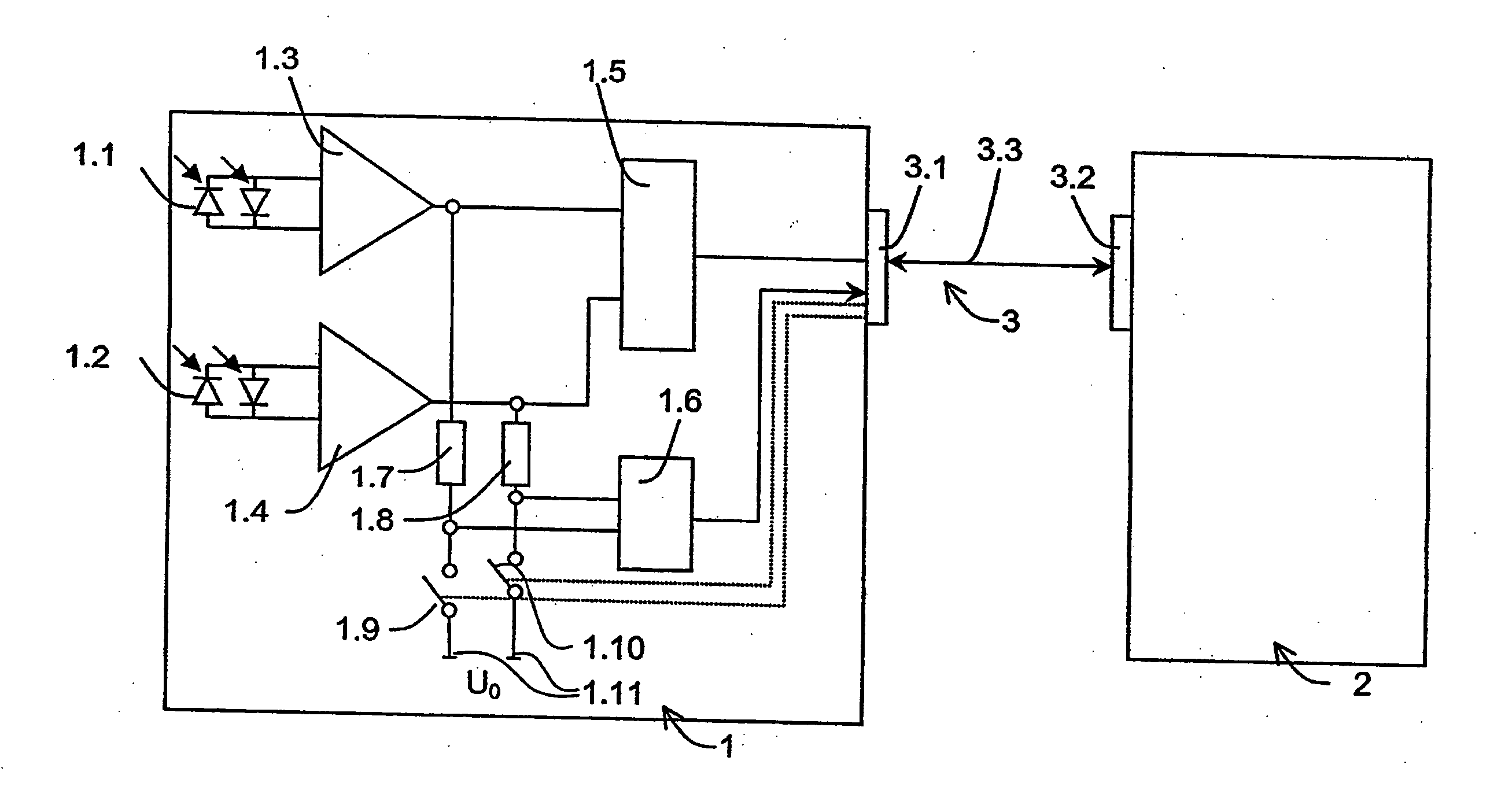
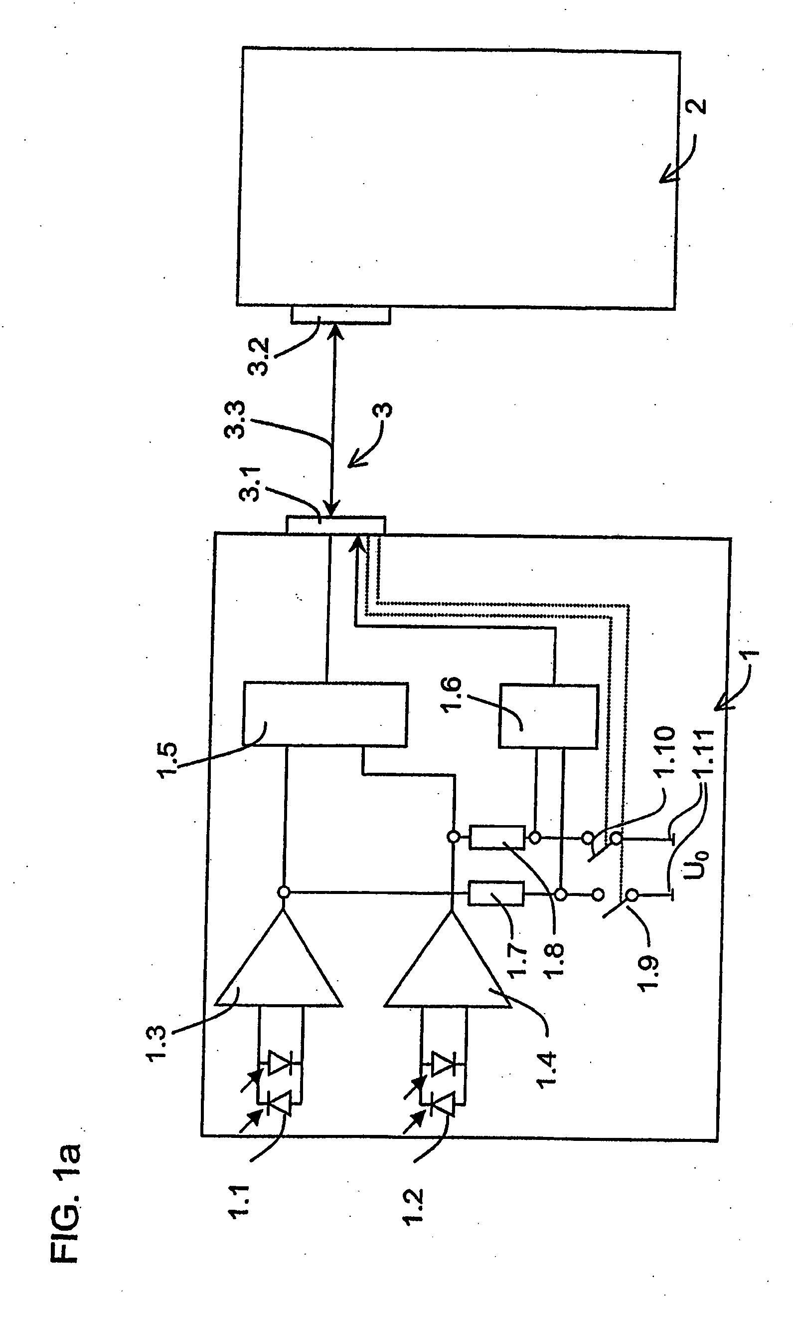
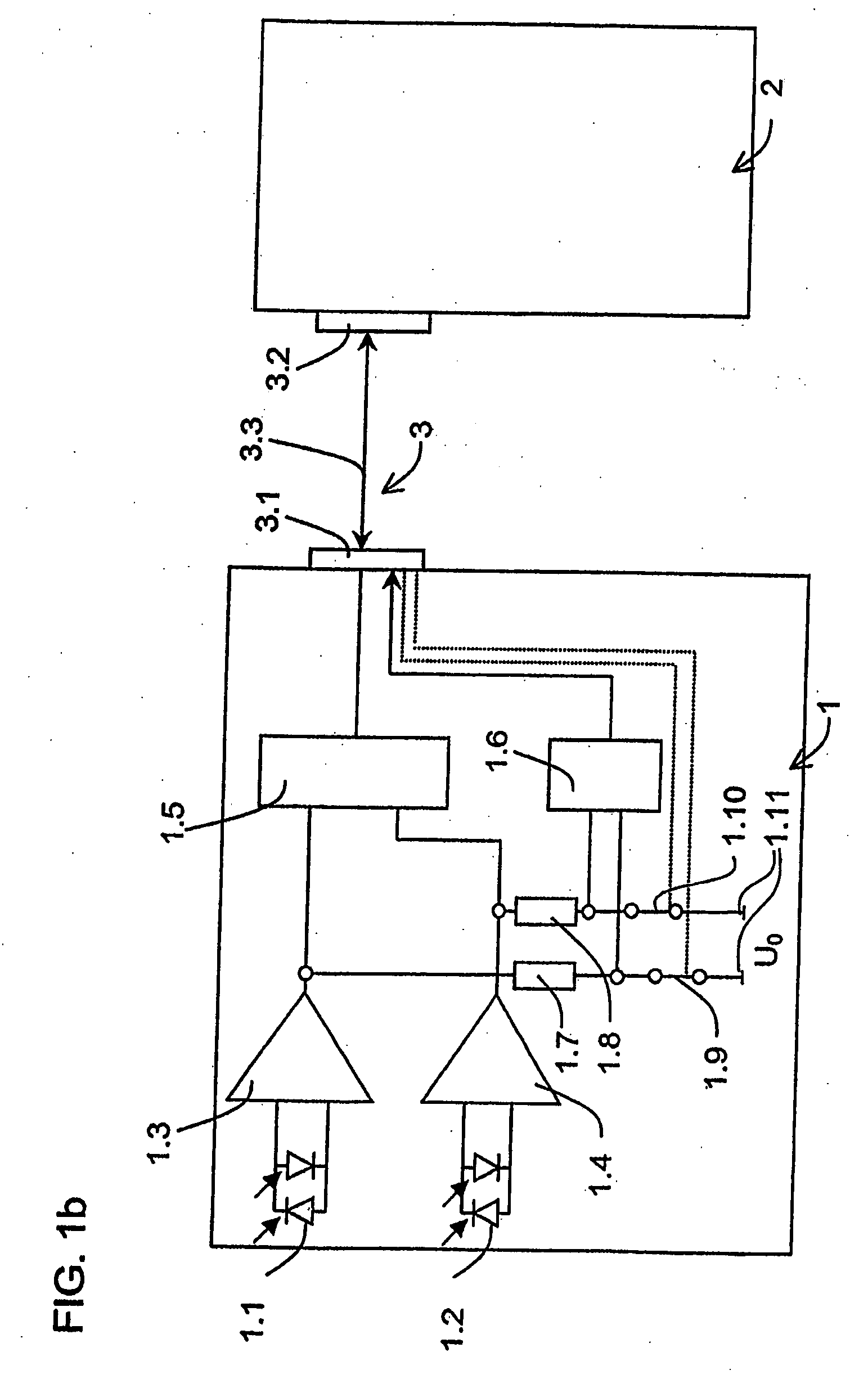
[0024] In FIG. 1a, a measuring system is illustrated, which includes a rotary transducer 1, a machine control 2, and a data-transmission device 3.

[0025] Rotary transducer 1 has photoelements 1.1, 1.2, amplifiers 1.3, 1.4, an evaluation electronics 1.5, and a signal-amplitude monitoring circuit 1.6. Arranged at the lines between amplifiers 1.3, 1.4 and evaluation electronics 1.5, are branch lines having resistors 1.7, 1.8. Disposed above that in the circuit of rotary transducer 1 are control elements 1.9, 1.10, which electrically contact a test potential source 1.11.

[0026] Control elements 1.9, 1.10 may assume two control element states. In the first control element state, test potential source 1.11 is isolated from signal-amplitude monitoring circuit 1.6, and in the second control element state, an electrical contact is established between test potential source 1.11 and signal-amplitude monitoring circuit 1.6.

[0027] Data-transmission device 3 includes an interface socket 3.1 at r...


PUM


Abstract

A measuring system includes a measuring device, another device and a device configured to transmit data enabling bits of data to be transmitted between the measuring device and the other device. The measuring device also includes a signal monitoring circuit and a switch element. The switch element is electrically contacted to a test potential source. The test potential source is in contact with the signal monitoring circuit according to a switch element state. The signal monitoring circuit is also in contact with the device for transmitting date. A method provides for functional monitoring of such a measuring system in a monitoring mode when a test potential is applied.

Description

CROSS-REFERENCE TO RELATED APPLICATION [0001] This application is a divisional of, and incorporates herein by reference in its entirety, prior application Ser. No. 10 / 529,421 which was filed on Mar. 25, 2005, which was a National Stage Application of PCT International Application No. PCT / EP03 / 09796.FIELD OF THE INVENTION [0002] The present invention relates to a measuring system, e.g., a position-measuring system, the functioning of which may be simple to test. The present invention is also directed to a method for testing for correct functioning. BACKGROUND INFORMATION [0003] In position-measuring systems, position sensors in a measuring device generate electrical signals, which provide information on the position of objects which are moving in relation to one another. The present invention relates to measuring systems that use measuring devices which produce comparatively precise, incremental positional information, as well as relatively rough positional information. These two typ...

Claims


Application Information

Patent Timeline
Patent Type & Authority Applications(United States)
IPC IPC(8): G06F19/00G01D3/08G01D5/244G01D5/36G01D18/00
CPCG01D3/08G01D18/00G01D5/36G01D5/24461
Inventor HOFBAUER, HERMANNSTRASSER, ERICH
Owner DR JOHANNES HEIDENHAIN GMBH
Learn More