Dryer having heater-installed suction duct

a dryer and suction duct technology, which is applied in the field of dryers, can solve the problems of air heated to have a predetermined temperature or more by the heater experiencing heat loss while flowing into the drum, malfunction or damage of the dryer, and the inability to reduce the distance between the heater and the drum to a predetermined distance or less, etc., to achieve easy overhaul or replacement of the heater, suppress heat loss, and suppress heat loss

Inactive Publication Date: 2007-11-08
DAEWOO ELECTRONICS CO LTD
View PDF99 Cites 25 Cited by
  • Summary
  • Abstract
  • Description
  • Claims
  • Application Information

AI Technical Summary

Benefits of technology

[0014] The present invention has been made to solve the above problems, and an aspect of the present invention is to provide a dryer having a heater-installed suction duct that can suppress heat loss during flow of air into a drum after being heated by a heater. Another object of the present invention is to provide the dryer having the heater-installed suction duct that can prevent unduly heated air from being blown into the drum while suppressing the heat loss during flow of hot air supplied through the heater. Yet another object of the present invention is to provide the dryer having the heater-installed suction duct that can permit easy overhauling or replacement of the heater.

Problems solved by technology

The conventional dryer constructed as above has a problem in that, since a separate duct extending from the suction duct so as to install the heater therein is located inside the cabinet, a distance between the heater and the drum cannot be reduced to a predetermined distance or less, so that air heated to have a predetermined temperature or more by the heater experiences heat loss while flowing into the drum.
Furthermore, the conventional dryer has a problem in that, since both the motor and heater likely to be overheated are installed within the cabinet without being separated, the interior of the cabinet is likely to be unduly overheated, causing malfunction or damage of the dryer resulting from overheating of the motor.

Method used


Image

  • Dryer having heater-installed suction duct
  • Dryer having heater-installed suction duct
  • Dryer having heater-installed suction duct

Examples


first embodiment

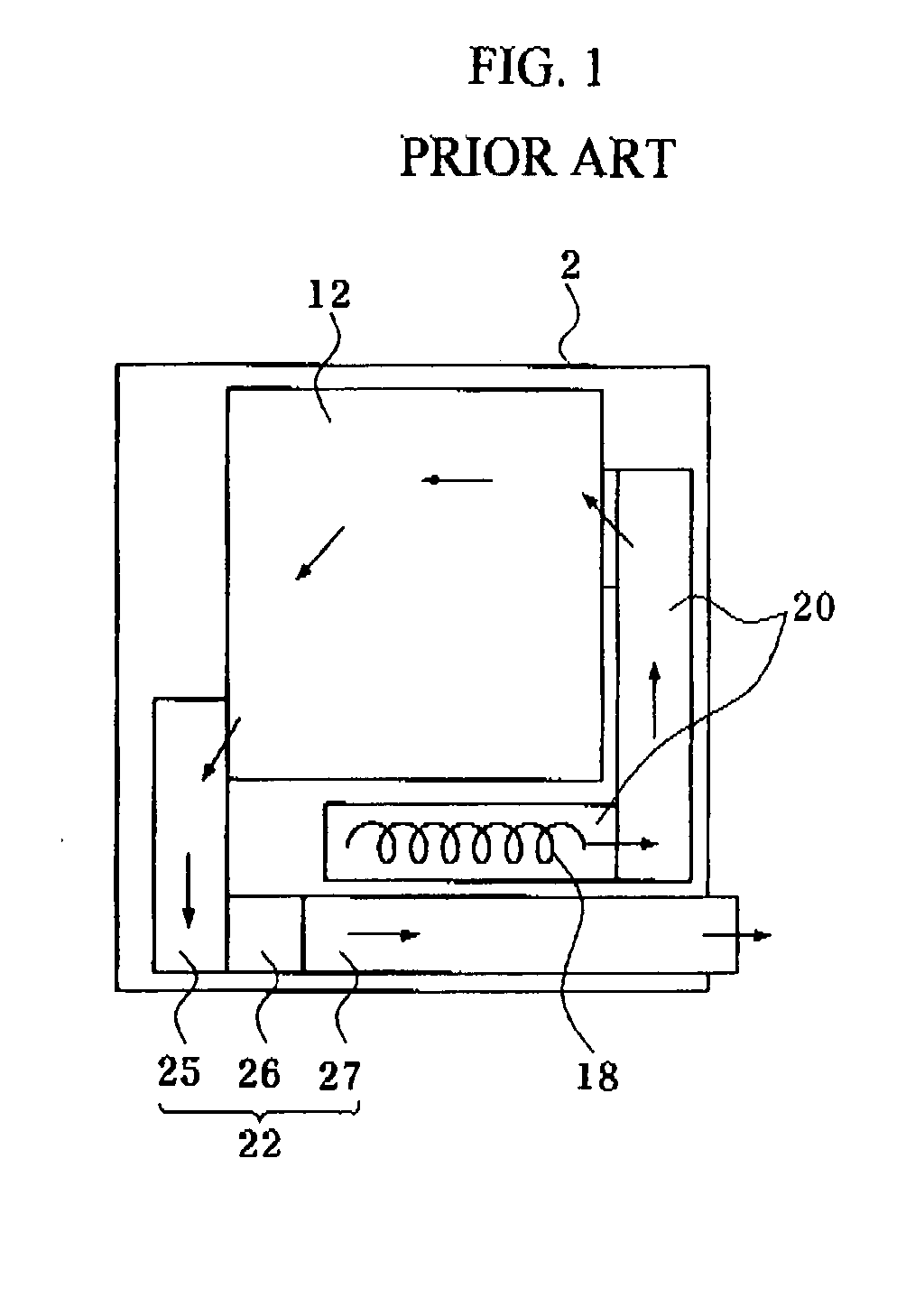
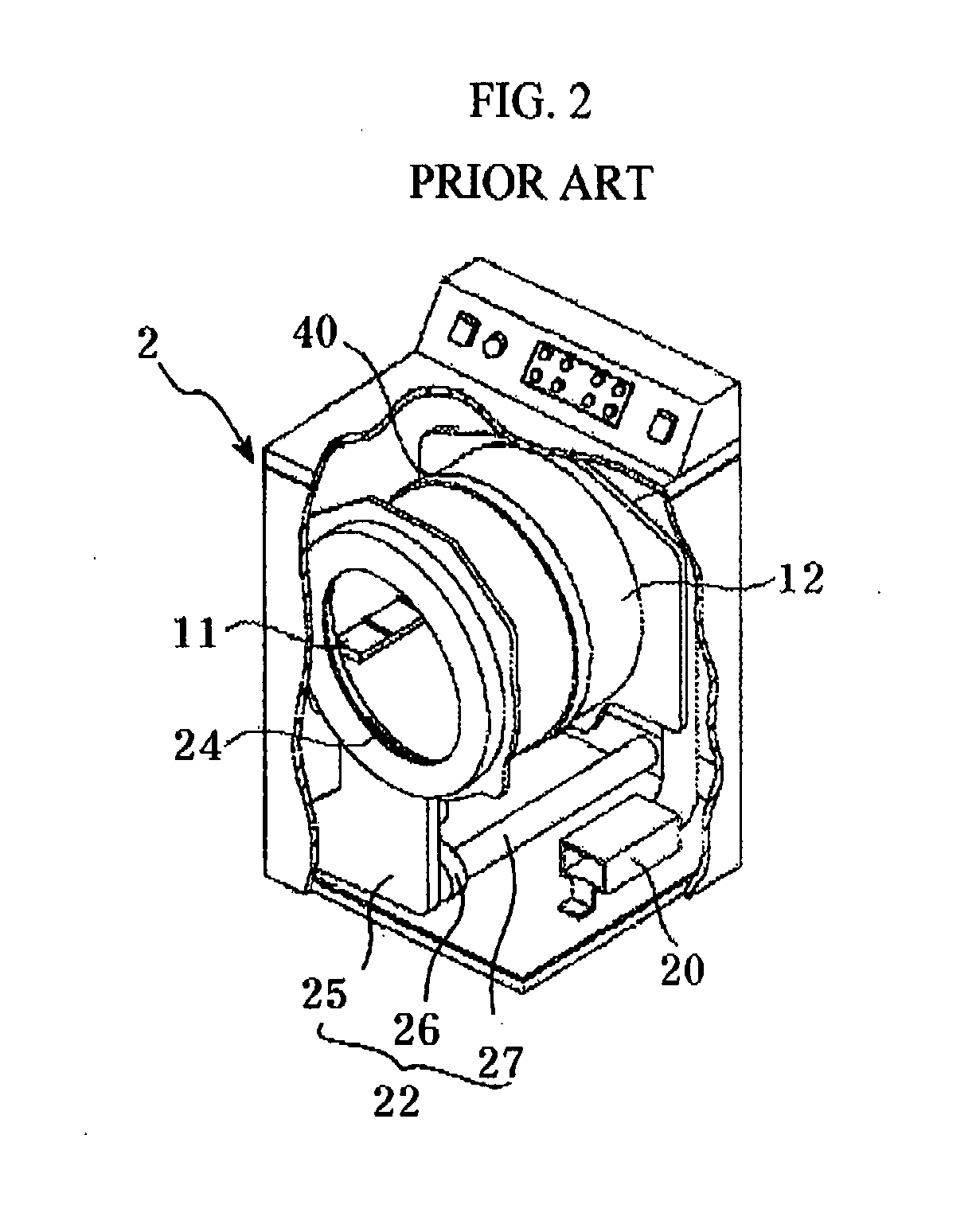
[0046] Referring to FIGS. 3 to 5, the dryer comprises: a cabinet 50 having an exhaust port 54 and an opening formed at one side thereof; a drum 60 rotatably installed inside the opening within the cabinet 50 to accommodate clothes; a lifter 100 formed on an inner wall of the drum 60 to rotate the clothes; a suction duct 70 having a suction port 52 to guide air inside the cabinet 50 into the drum 60; a heater 74 installed in the suction duct 70; an exhaust fan 82 disposed between the drum 60 and the exhaust port 54; an exhaust duct 80 disposed between the exhaust fan 82 and the exhaust port 54; and a driving motor 90 connected to a rotational shaft of the exhaust fan 82.

[0047] When power is applied to the motor 90 by handling of a user, the exhaust fan 82 is rotated to circulate air. Air is heated by the heater 74 while passing through the heater 74 and supplied into the drum 60 where the air is brought into contact with clothes to dry or sterilize the clothes. When air is exhausted...

second embodiment

[0069] Next, a dryer having a heater-installed suction duct according to the present invention is described in detail with reference to the accompanying drawings.

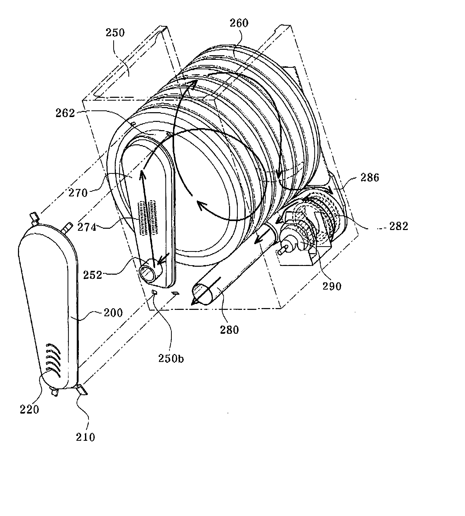
[0070]FIG. 14 is a rear exploded perspective view of a dryer according to the second embodiment, FIG. 15 is a front exploded perspective view of the dryer according to the second embodiment, FIG. 16 is a rear perspective view illustrating an exhaust port of the dryer according to the second embodiment, FIG. 17 is a front perspective view illustrating a suction duct of the dryer according to the second embodiment, FIG. 18 is a sectional side elevation illustrating a suction flow path of the dryer according to the second embodiment, and FIG. 19 is a plan view illustrating an exhaust flow path of the dryer according to the second embodiment.

[0071] Referring to FIGS. 14 to 19, the dryer according to the second embodiment comprises: a cabinet 250 having an exhaust port 254 and an opening formed at one side thereof; a drum 260 r...


PUM


Abstract

Disclosed herein is a dryer having a heater-installed suction duct. The dryer can suppress heat loss while heated air is supplied to the drum, minimizing energy loss in the dryer, and can permit overhauling or replacement of the heater. The dryer comprises a cabinet having an exhaust port and an opening to which a door is provided, a drum rotatably located within the cabinet to accommodate clothes, a holding panel installed to an inner wall of the cabinet and having a through-hole part formed in the holding panel with the drum rotatably connected to the holding panel, a suction duct extending from the through-hole part, and a heater installed in the suction duct to heat air flowing into the drum. The dryer further comprises a cover detachably mounted to a hole formed in a rear side of the cabinet corresponding to the suction duct.

Description

BACKGROUND OF THE INVENTION [0001] 1. Field of the Invention [0002] The present invention relates to a dryer, and, more particularly, to a dryer having a heater-installed suction duct that can suppress heat loss while air heated by a heater is supplied into a drum, thereby minimizing energy loss in the dryer. [0003] 2. Description of the Related Art [0004]FIG. 1 is a diagram illustrating a flow path of a conventional dryer and FIG. 2 is a partially cut-away perspective view of the conventional dryer. [0005] Referring to FIGS. 1 and 2, the conventional dryer comprises a cabinet 2 adapted to define an outer appearance and having a clothes inlet / outlet opening formed in the front side of the cabinet 2, a drum 12 rotatably installed within the cabinet 2 to accommodate clothes and opened in front and rear directions to allow air to pass therethrough, a heater 18 installed within the cabinet 2 to heat intake air, a suction duct 20 to guide heated air having passed through the heater 18 to...

Claims


Application Information

Patent Timeline
Patent Type & Authority Applications(United States)
IPC IPC(8): F26B11/02
CPCD06F58/02D06F58/26D06F58/20
Inventor KIM, CHANG HOOKIM, KYOUNG HAK
Owner DAEWOO ELECTRONICS CO LTD
Why Eureka
Try Eureka