Liquid-liquid heat exchanger

A technology of heat exchangers and exchangers, applied in heat exchange equipment, water heaters, fluid heaters, etc., can solve the problems of worsening concentricity, high cost, and many working hours, and achieve the effect of reducing working hours and cost

Inactive Publication Date: 2006-08-02
RINNAI CORP
View PDF1 Cites 5 Cited by
  • Summary
  • Abstract
  • Description
  • Claims
  • Application Information

AI Technical Summary

Problems solved by technology

At this time, it is necessary to simultaneously bend the inner tube and the outer tube while maintaining the concentricity, but this operation is extremely difficult.
In particular, if the double pipe is bent with a small radius of curvature, the concentricity of the inner pipe and the outer pipe is extremely deteriorated, so the radius of curvature of the double pipe cannot be increased.
Therefore, it is impossible to precisely bend the double-layer pipe with a sma...

Method used


Image

  • Liquid-liquid heat exchanger
  • Liquid-liquid heat exchanger
  • Liquid-liquid heat exchanger

Examples


Embodiment Construction

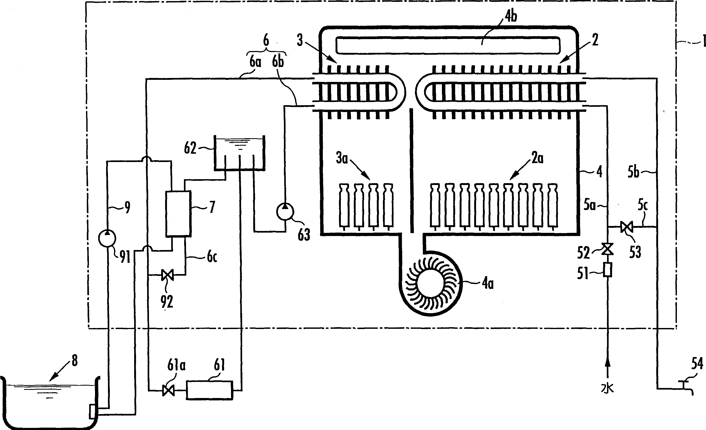
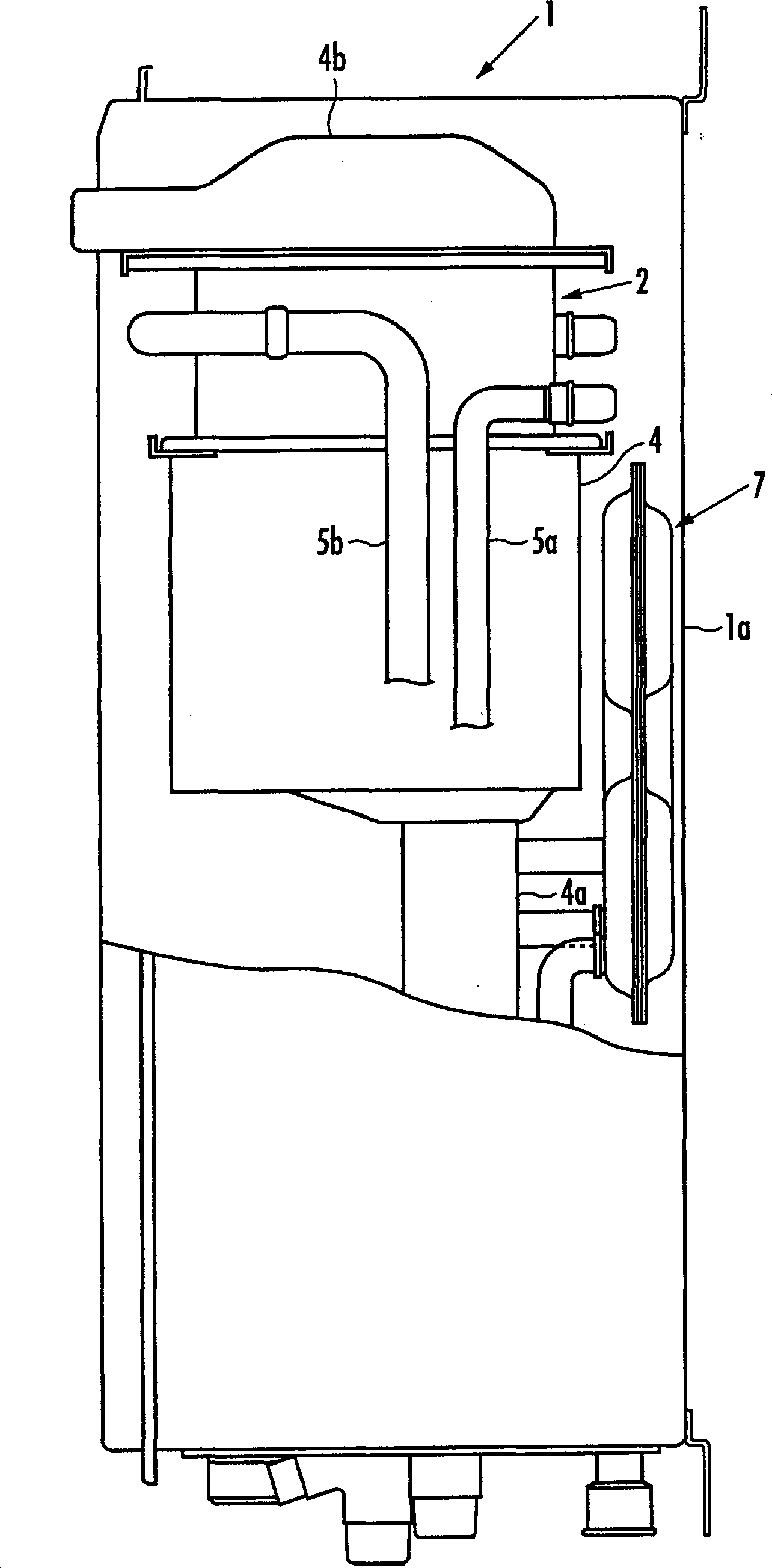
[0018] refer to figure 1 , 1 denotes a heat source machine including the heat exchanger 2 for hot water supply and the heat exchanger 3 for heating. The two heat exchangers 2 and 3 for hot water supply and heating are arranged side by side on the upper part of the tank body 4 arranged in the heat source machine 1 . At the bottom of the tank body 4, a hot water supply burner 2a as a heat source of the hot water supply heat exchanger 2 and a heating burner 3a as a heat source of the heating heat exchanger 3 are arranged side by side. 4, the combustion of each burner 2a, 3a is carried out using the air supplied from the blower 4a below it as combustion air. In addition, an exhaust passage 4b ​​for exhausting combustion exhaust gas passing through the respective heat exchangers 2 and 3 is provided above the tank body 4 .

[0019] The water supply path 5 a on the upstream side and the outlet hot water path 5 b on the downstream side are connected to the heat exchanger 2 for hot w...


PUM


Abstract

The present invention provides a liquid-liquid heat exchanger comprising a first flow channel where a heat medium heated by the heat exchanger applying a burner mounted on a heat source machine as its heat source flows, and a second flow channel where heated liquid flows, and heating the heated liquid by the heat medium. Three sheets of press-formed plates composed of first and second outer plates 71, 72 and an intermediate plate 73 held between the outer plates are overlapped. The first flow channel 74 having the bent-pipe shape is formed between the first outer plate 71 and the intermediate plate 73, and the second flow channel 75 having the bent-pipe shape, is formed between the second outer plate 72 and the intermediate plate 73 so as to overlap the first flow channel 74 through the intermediate plate 73. The invention miniaturizes a liquid-liquid heat exchanger and to reduce its cost.

Description

technical field [0001] The invention relates to a liquid-liquid heat exchanger, which has: a first flow passage, which circulates a heat carrier heated by a heat exchanger provided in a heat source machine as a heat source; a second flow passage, which circulates The liquid to be heated heats the liquid to be heated flowing in the second flow path by passing through the heating medium flowing in the first flow path. Background technique [0002] As is well known, conventionally, in a heat source machine having heat exchangers for hot water supply and heating using a burner as a heat source, a liquid-liquid heat exchanger having a first flow passage and a second flow passage is provided, thereby enabling The additional heating of the bath water is carried out, wherein the first flow path flows a heating medium such as antifreeze heated by the heating heat exchanger, and the second flow path flows bath water. [0003] Here, the liquid-liquid heat exchanger for additional heat...

Claims


Application Information

Patent Timeline
IPC IPC(8): F28D9/00
CPCF24H1/14F24H1/40F24H1/52F24H9/1836F28F3/005
Inventor 成濑英克竹内誉树
Owner RINNAI CORP
Why Eureka
Try Eureka