Method of designing product using 3-dimensional model

a technology of three-dimensional models and products, applied in the direction of total factory control, programme control, instruments, etc., can solve the problems of large development time and trial cost, development time, and the inability to apply the three-dimensional model of rough models to the machining data for mold manufacturing, so as to reduce the man-hour of manufacturing and the effect of tes

Inactive Publication Date: 2005-04-19
HONDA MOTOR CO LTD
View PDF8 Cites 23 Cited by
  • Summary
  • Abstract
  • Description
  • Claims
  • Application Information

AI Technical Summary

Benefits of technology

[0016]Compared with the prior method which performed a CAE analysis for a rough model, which had a rather different shape from that of the product, according to claim 1 of the present invention, a CAE analysis is performed for the CAE model representing the product shape in detail and the drawings for the product are prepared on the basis of the results. As it makes possible to find errors in the design associated with strength and performance in advance of the trial manufacturing, the more matured design will be attainable. Therefore, the drawings for trial and mass production will be more matured, thereby leading to a reduction in the time period of testing and the labor costs for the development.
[0020]In this method, a rough model dedicated to the use for CAE analysis is not requested, since the CAE analysis is performed for the three dimensional CAE model, which is applicable to the data for manufacturing the trial product. Because the three dimensional CAM model is prepared at the beginning of trial manufacturing, the man-hour of manufacturing can be reduced by utilizing it for the trial manufacturing, and also the man-hour of test is decreased by performing the test with the trial product closer to the final mass production product.

Problems solved by technology

However, as the iteration of trial requires a large amount of development time and trial cost, in recent years it has been tried to reduce the development time utilizing the analytical technique of CAE (Computer Aided Engineering).
It means that the three-dimensional model of the rough model cannot be applied to the machining data for the mold manufacturing.
The reason why the rough model was used in the prior CAE analysis is that the CAM model, the data of which deserved to be applied to the machining data of the mold manufacturing, could not be brought into use in the actual development.
It was extremely difficult to divide the CAM model into meshes due to its data size and fineness, and it took too much time to perform the stress calculation etc. even if the mesh dividing was performed successfully.
Metal molds are much more expensive than sand molds, and it will be a great waste when such changes come up later that require more than the mold correction.
However, the development flow with CAE analysis mentioned before was not efficient in the following points.
The rough model did not incorporate the detailed shape of product, not allowing checking the effects of reinforcement with fillets and ribs to end up with many unanticipated defects in the trial product of sand mold sometimes. Therefore, the test of the trial product of sand mold was liable to be delayed, and it required several times of the iteration depending on the degree of completion.
It is attributed to the fact that the product has to be made thicker because the sand mold is inferior to the metal mold in the accuracy of shape and is not able to withstand the pressure.
Therefore, the product of sand mold tends to have excessive strength than that of metal mold.
In other words, the strength of the product is liable to be insufficient when it is manufactured with a metal mold.
Unanticipated defects happened to emerge in the stage of mass production confirmation, which led to the correction or re-manufacture of metal mold, caused the increase in the development period of time and cost.

Method used


Image

  • Method of designing product using 3-dimensional model
  • Method of designing product using 3-dimensional model
  • Method of designing product using 3-dimensional model

Examples


Embodiment Construction

[0022]The preferred embodiment of the present invention will now be described in detail below.

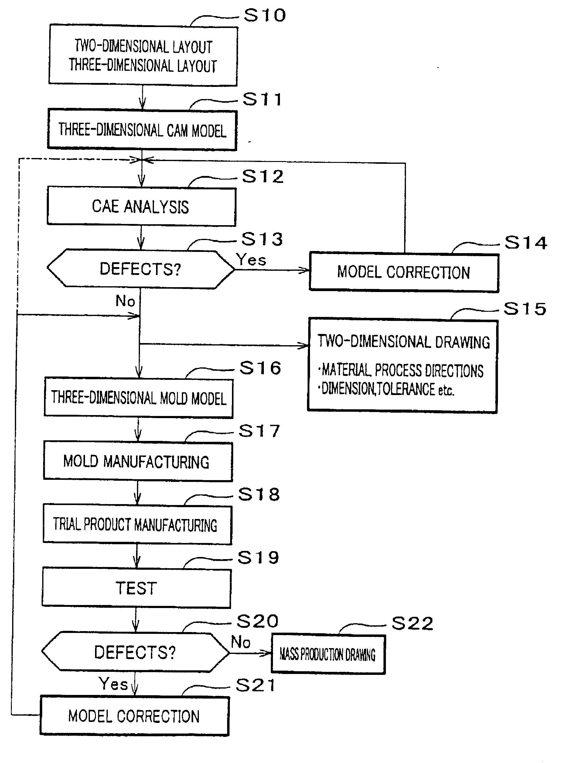
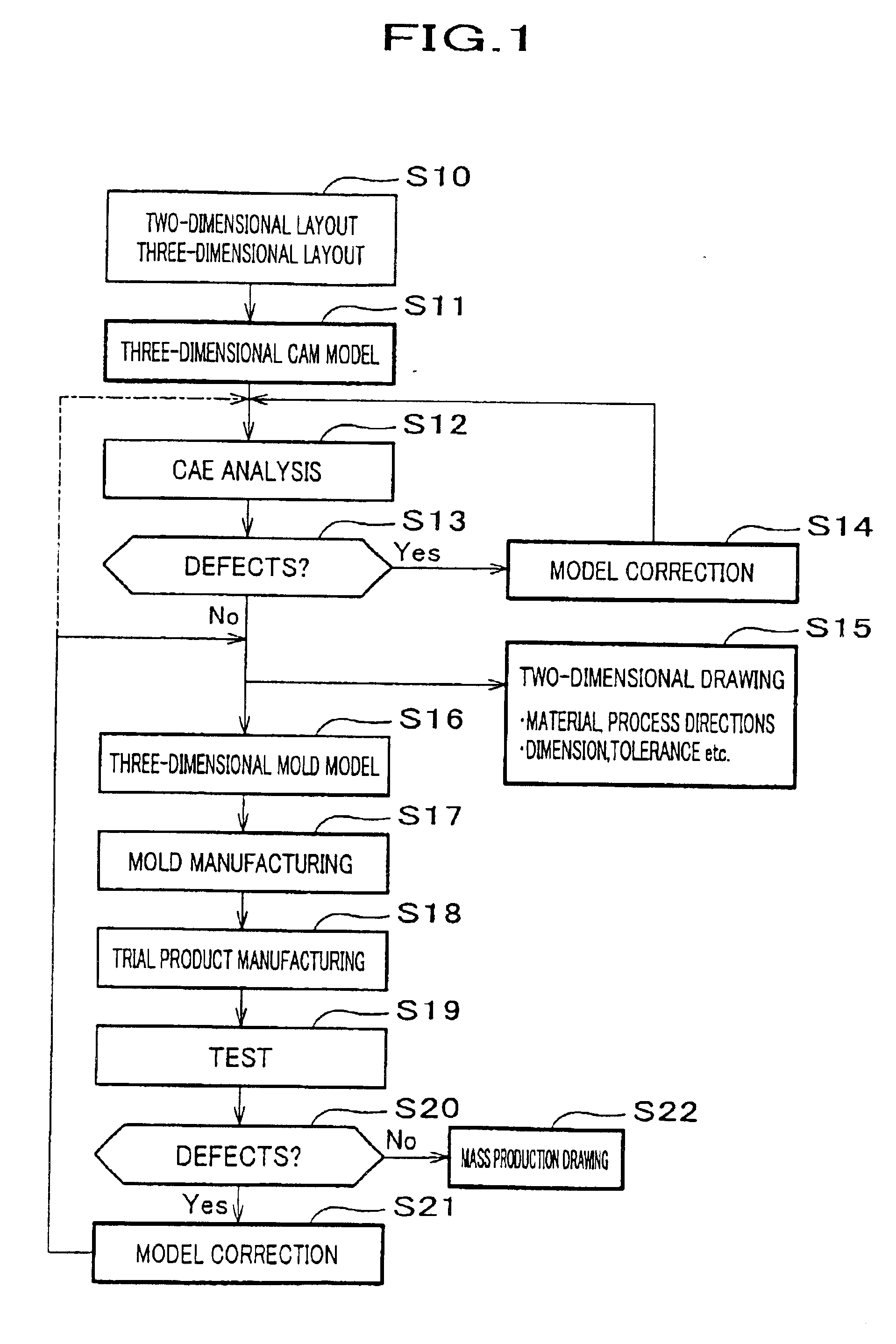
[0023]FIG. 1 is a flow diagram describing a design method of a product with three-dimensional model.

[0024]A designer prepares two-dimensional layout drawings or a three dimensional layout model with a three-dimensional CAD system (S10). He then makes a three dimensional CAM model for each part or some parts in the three-dimensional CAD system (S11) and performs the CAE analysis for it (S12). The stress analysis for the three dimensional CAM model is conveniently performed in the three-dimensional CAD system, which has been developed recently. An expert on CAE analysis used to prepare a meshed model appropriate for the shape of each part and perform the calculation and post-calculation displaying process. Now dividing a complex shape like a three-dimensional CAM model into meshes, the calculation and the post-calculation displaying process can be performed automatically. Therefore, an expert...


PUM


Abstract

The present invention provides a design method, which makes the product development more efficient. The design is performed with the process including the following steps; a first step to prepare a three-dimensional CAM model S11, a second step to perform a CAE analysis for the three-dimensional CAM model S12, a third step to correct the three-dimensional CAM model on the basis of the CAE analysis if the defects exist S14, a fourth step to manufacture a mold on the basis of the three-dimensional CAM model S17, a fifth step to manufacture a trial product with the mold S18, a sixth step to test the trial product S19, a seventh step to correct the three-dimensional CAM model if the defects exist S21, an eighth step to iterate the fourth through seventh steps until the defects are solved (S21, S16 through S20), a ninth step to prepare the drawings on basis of the three-dimensional CAM model obtained at the eighth step S22.

Description

FIELD OF THE INVENTION[0001]The present invention relates to a design method of a product with three-dimensional CAM (Computer Aided Manufacturing) model, which enables a reduction in man-hours associated with the product development.BACKGROUND OF THE INVENTION[0002]Generally speaking, a process is required to complete the design of a product, in which two-dimensional drawings are prepared and the manufacturing of a trial product with them and testing are performed to dig out its defects, followed by the update of the drawings for further maturity. However, as the iteration of trial requires a large amount of development time and trial cost, in recent years it has been tried to reduce the development time utilizing the analytical technique of CAE (Computer Aided Engineering).[0003]The product design flow with the prior CAE analysis is described as follows. FIG. 2 is a figure showing the flow diagram for a product design with the prior CAE analysis.[0004]A designer prepares two-dimen...

Claims


Application Information

Patent Timeline
Patent Type & Authority Patents(United States)
IPC IPC(8): G05B19/00G05B19/4097G05B19/4099G06F17/50
CPCG05B19/00G05B19/4099G06F17/50G06F2217/41G05B2219/45204G06F30/00G06F2113/22Y02P90/02
Inventor UCHIDA, TAKANAOSHIMADA, HIROMINAGAI, SHIGERU
Owner HONDA MOTOR CO LTD
Why Eureka
Try Eureka