Ceiling fan

a ceiling fan and fan body technology, applied in the direction of positive displacement liquid engine, piston pump, liquid fuel engine, etc., can solve the problems of unnecessary press process in multiple operations, and achieve the effect of reducing the shaking and vibration of the motor associated with the rotation of the bearing housing, low noise and low vibration

Active Publication Date: 2010-02-18
PANASONIC CORP
View PDF4 Cites 21 Cited by
  • Summary
  • Abstract
  • Description
  • Claims
  • Application Information

AI Technical Summary

Benefits of technology

[0010]With this structure, shaking and vibration of the motor associated with the rotation of the bearing housing can be significantly reduced, and thus the present invention can offer the ceiling fan with low noise and low vibration. In addition, a press process in multiple operations become unnecessary. This can reduce a damage to the ball bearing in an assembly process as well as reduction of manhour.

Problems solved by technology

In addition, a press process in multiple operations become unnecessary.

Method used


Image

  • Ceiling fan
  • Ceiling fan
  • Ceiling fan

Examples


first exemplary embodiment

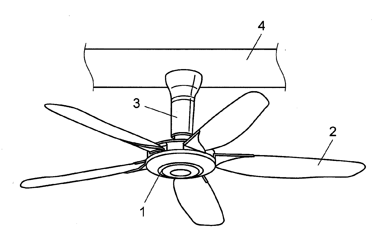
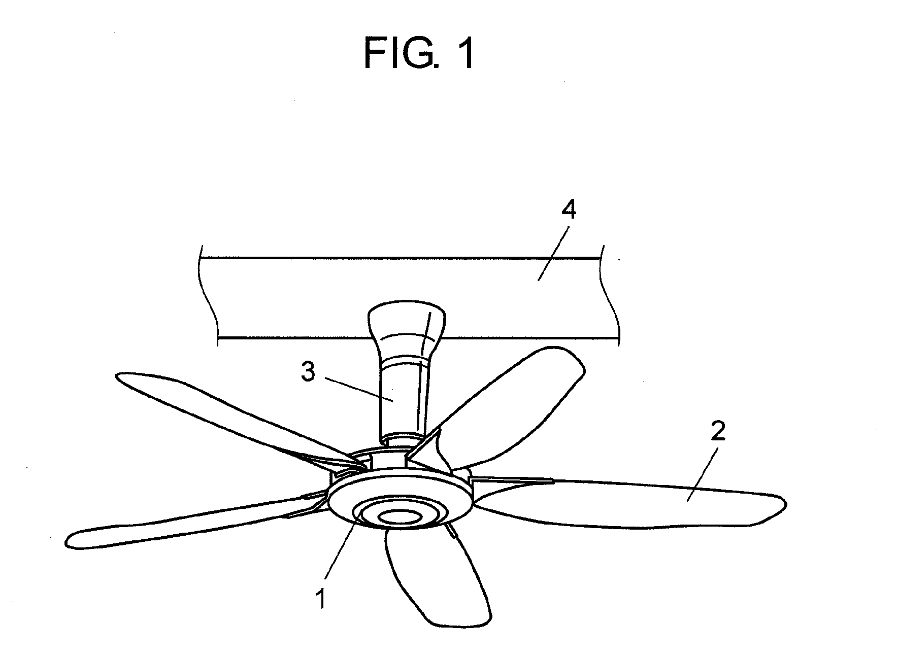
[0075]FIG. 1 illustrates a basic structure of a ceiling fan in the first exemplary embodiment of the present invention. The ceiling fan in the first exemplary embodiment includes motor 1 that rotates multiple blades 2 provided in the horizontal direction. This motor 1 is suspended from ceiling 4 using suspension mechanism 3.

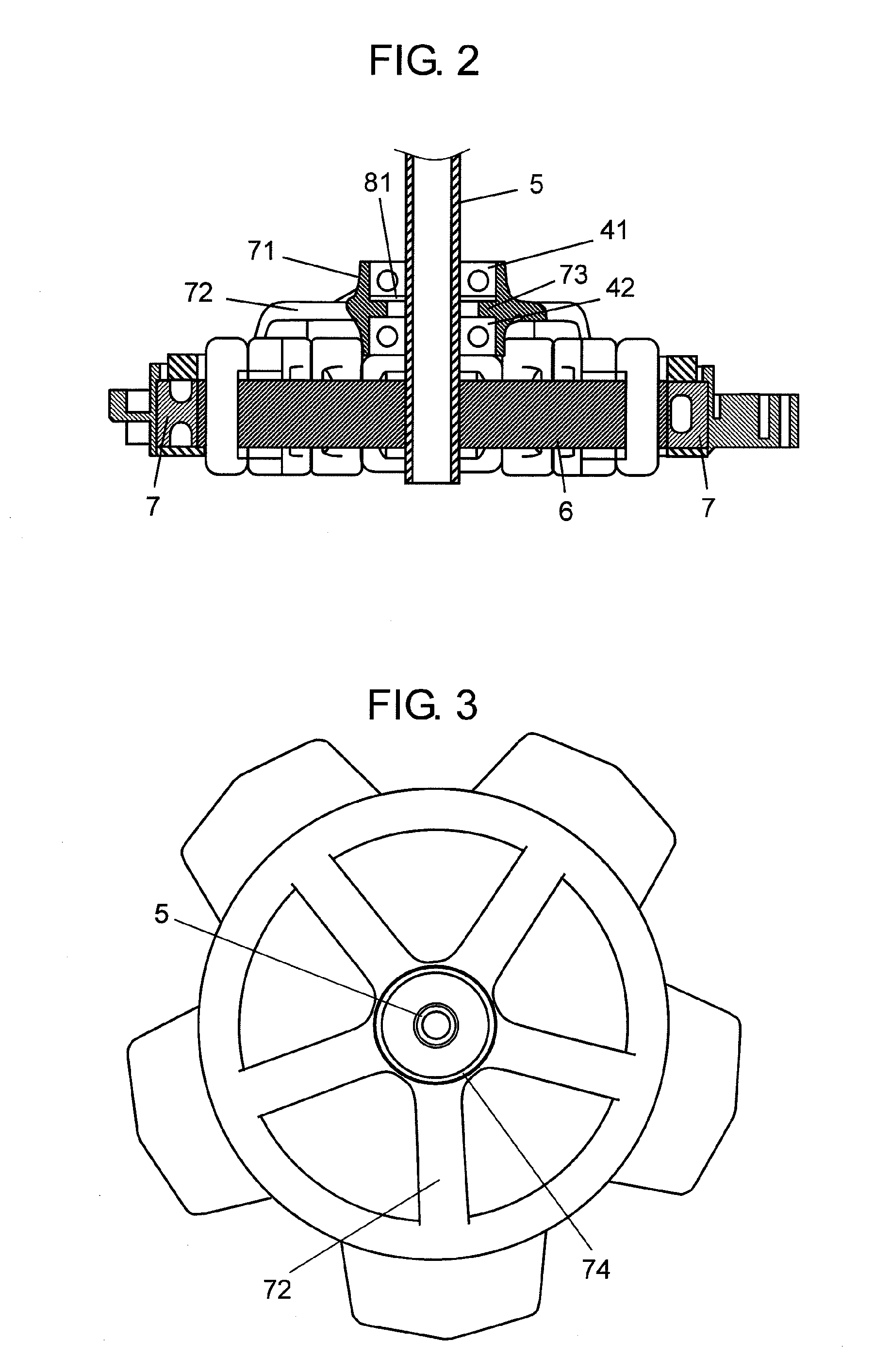
[0076]FIG. 2 is a sectional view of motor 1 of the ceiling fan in the first exemplary embodiment of the present invention. FIG. 3 is its top view, and FIG. 4 is its exploded sectional view. FIG. 5 is a schematic sectional view of a ball bearing in motor 1.

[0077]Motor 1 includes disc-like stator 6 to which hollow shaft 5 is disposed upright on its center, and rotor 7 rotatably provided around the outer periphery of this stator 6. Blade 2 is attached to rotor 7. Motor 1 further includes cylindrical bearing housing 71, rotor support 72 that integrally connects this bearing housing 71 and rotor 7, and a pair of upper ball bearing 41 and lower ball bearing 42 housed i...

second exemplary embodiment

[0097]FIGS. 11 and 12 are fragmentary sectional views of a suspension mechanism of a ceiling fan in the second exemplary embodiment of the present invention. FIG. 13 is a magnified view of its key part. Suspension mechanism 3 includes pipe 31 connected to hollow shaft 5 of motor 1 by connecting bolt 20, operation lever 35 for operating safety switch 15, and suspender 34 for suspending pipe 31 from ceiling 4. Hollow shaft 5 and pipe 31 have through hole 17, respectively, and they are connected by connecting bolt 20. Details are described later.

[0098]Motor cover 11 is provided on a top part of motor 1, and opening 12 is created on its top face. Safety switch 15 is fixed inside motor cover 11 to the side of hollow shaft 5. Operation lever 35 for operating this safety switch 15 includes fixing part 36 and arm 37 extending obliquely downward from this fixing part 36. Fixing part 36 is fixed to pipe 31, and arm 37 operates safety switch 15 through opening 12.

[0099]Safety switch 15 has ope...


PUM


Abstract

A ceiling fan includes a motor for rotating multiple blades. This motor includes a hollow shaft that is disposed upright on the center of a disc-like stator, and a rotor around an outer periphery of the stator. The rotor integrally rotates with the blades. This motor further includes a cylindrical bearing housing, and a pair of upper ball bearing and a lower ball bearing housed in this bearing housing. This bearing housing has a base in its center. The upper ball bearing is disposed over the base, and the lower ball bearing is disposed under the base in this bearing housing. Both bearings are fixed onto the hollow shaft.

Description

TECHNICAL FIELD[0001]The present invention relates to ceiling fans connected to a hollow shaft protruding upward from a motor that rotates blades, and a pipe suspending from the ceiling.BACKGROUND ART[0002]One known technology to prevent drop accidents due to loosened or detached screws in this type of conventional ceiling fans is to sound an alarm when an attached screw becomes loose. For example, this is disclosed in Patent Document 1.[0003]This ceiling fan is described below with reference to FIG. 17. As shown in the drawing, pipe 101 passing through the center of ceiling fan is suspended from bracket 103 via semi-spherical flange 102. Bracket 103 is attached to mounting plate 105 by attaching screw 106. This mounting plate 105 is attached to a ceiling face by wood screw 104. Microswitch 107 is provided on bracket 103, and actuator 108 of microswitch 107 makes contact with the ceiling face.[0004]To increase the safety, an alarming device is activated via microswitch 107 when wood...

Claims


Application Information

Patent Timeline
Patent Type & Authority Applications(United States)
IPC IPC(8): F04B17/03F04D29/60
CPCF04D29/059F04D25/088
Inventor YAMAMOTO, KIMINOBUKAWAZU, TETSUJIYOSHIKAWA, HIROSHIIWAMOTO, KIYOHIKOTANIMURA, YOSHIKI
Owner PANASONIC CORP
Why Eureka
Try Eureka