Facer beam barrier system

a technology of facer beams and barriers, applied in the field of facer beam barrier systems, can solve the problems of bowdens system not teaching a method of ease and efficiency for collateral extension in a vertical direction, bowdens and chapmans both lack the ability to remove plywood modules, and the barrier installation process is not complete. the effect of man-hours and dramatic reduction of variable costs

Inactive Publication Date: 2006-07-20
NELSON THOMAS PAGE
View PDF0 Cites 21 Cited by
  • Summary
  • Abstract
  • Description
  • Claims
  • Application Information

AI Technical Summary

Benefits of technology

[0035] The Facer Beam Barrier System is advancement in barriers, for the purpose of reducing man-hours in barrier installations. When fixed costs reduce variable cost, and when fixed cost is not significantly increased while variable costs are dramatically decreased, an economical advantage for the average consumer results.

Problems solved by technology

Bowden teaches a method of extending transverse sub-members in repetition with the ability to overlap and stabilize a plurality of collateral vertical wales, he does not teach a method of ease and efficiency for extending his materials collaterally in a vertical direction.
Bowdens system does not complete formwork application and removal with the ease, versatility, and competence of the facer beam system claimed herein.
Bowden and Chapman both lack the ability to remove plywood modules, or to remove subordinate beams with ease.
Menchetti fails to recognize a method of overlapping subordinate beam members and he does not reveal a method of incorporating the main member or super-ordinate beam as a facer beam.
Menchetti's art does not address issues related to formwork such as self-contained; staging brackets, beam connections, lifting eyes and self contained fastening systems (his fastening system is applied to each facer panel and is not a function of the main beam member).
These large companies control the market and they shape the market to require their rental products and most of their rental products do not integrate with the competition.

Method used


Image

  • Facer beam barrier system
  • Facer beam barrier system
  • Facer beam barrier system

Examples


Embodiment Construction

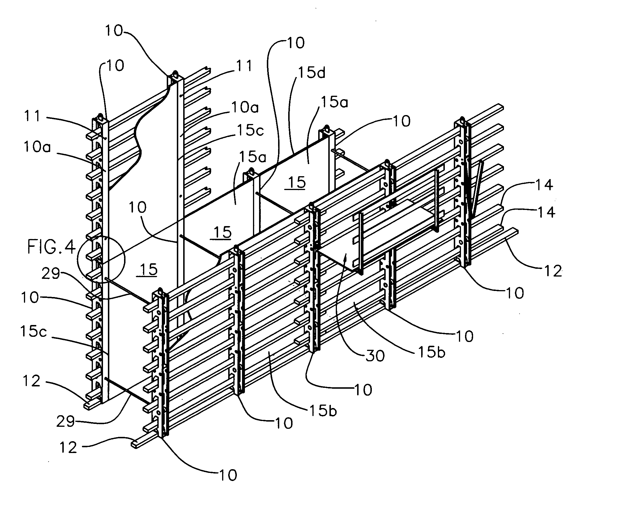
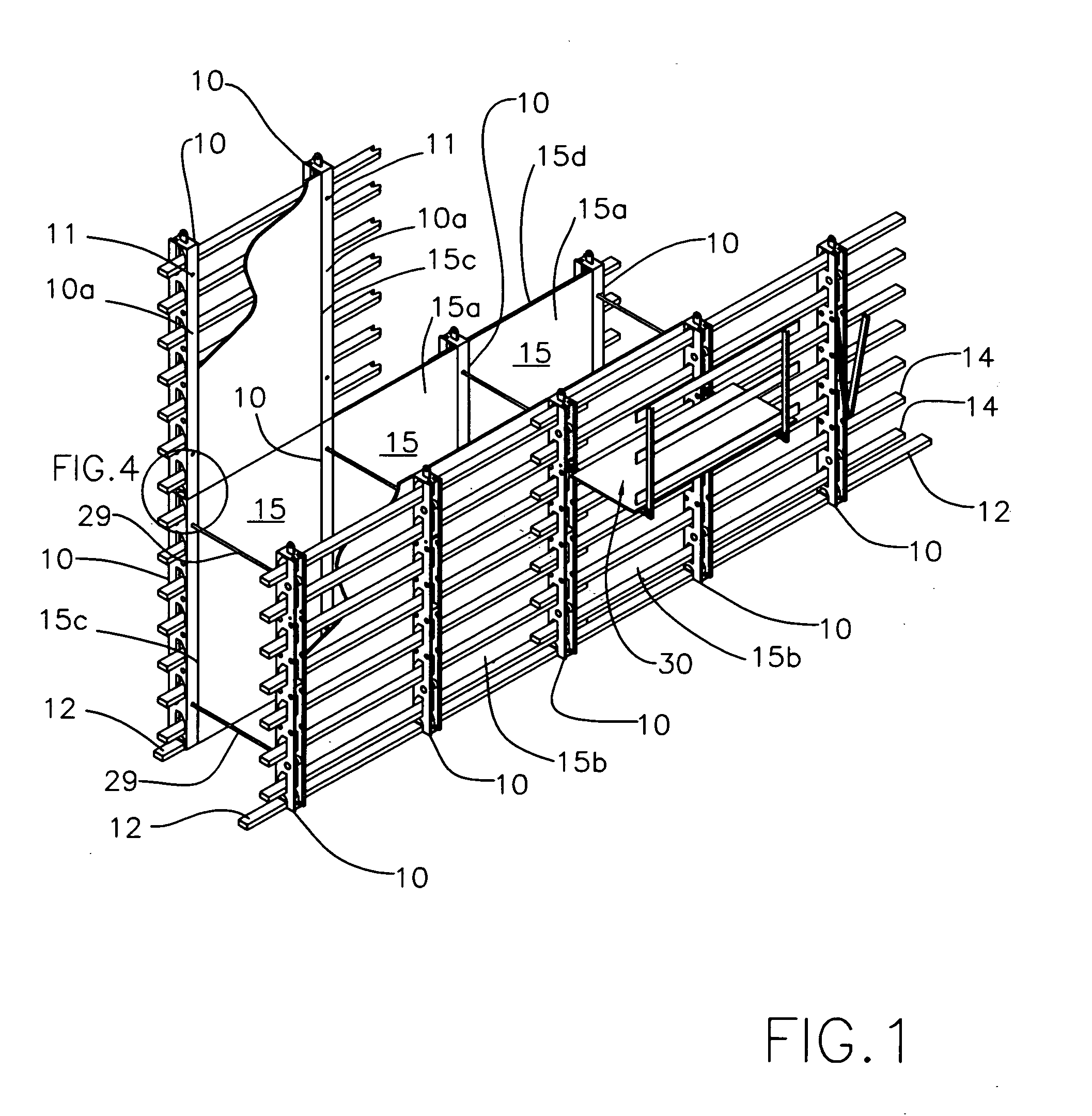
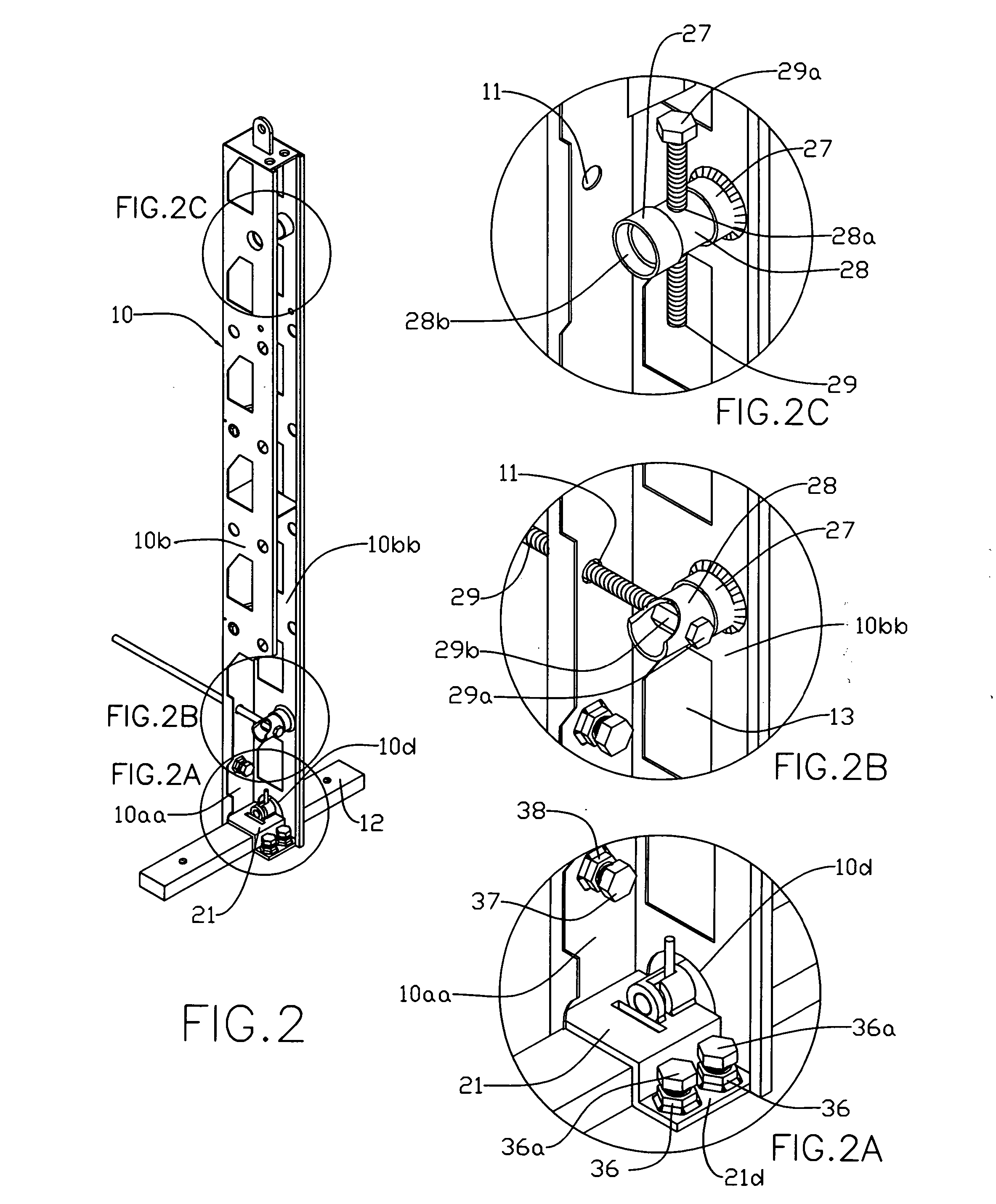
[0075] The description provided herein explains the manufacture, assembly, disassembly and storage of the components of the Facer Beam Barrier System. Its versatile nature in meeting barrier requirements will be obvious to those schooled in the construction and use of barriers. As shown in the drawings like numerals represent like parts throughout the various views and the following description will be clear with reference to the drawing figures and views as numbered in the description.

[0076]FIG. 1 displays erected barriers used as concrete formwork and further displays a plurality of identical, elongated, multi-functional, super-ordinate, opened back box type ┌┐-facer beams 10 (FIGS. 1 and 2) arranged in parallel segments, with side webs 10b (FIG. 2) of box beams 10 generally wider than the face 10a (FIG. 1) and the open back of box beams 10, webs 10b are shaped by bending 90 degrees back and away from face 10a, webs 10b also have a deformed return lip 10c (FIG. 3) located at the ...


PUM


Abstract

This invention expands Nelson's Sub-Rigid Fast-Form Barrier System that it was originally a part of. The system disclosed herein is simple to manufacture and simple to use and promises wide commercial application as the labor costs for concrete construction become increasingly prohibitive. The extraordinary absence of nails, screws, bolts, welds or any other fastening device allows these barriers to compete with many conventional barrier systems and any concrete form system on the market today. The invention addresses eccentric beam loading where barriers must be economically fabricated to withstand liquid concrete pressure in a sub-rigid manner. While providing a lightweight beam with heavy weight strength it is also a goal of this invention to provide a form system that is self-contained, meaning that all fasteners to construct the barrier, ties that hold form barriers together, staging needed to erect the barriers, bolts used to plumb the barriers and brackets available to hoist the barriers are all integral parts of this invention. Another goal disclosed herein are barriers for concrete formwork that are made up of ninety percent standard building products found in any locality in the world. This barrier invention offers rapid erection time that can be accomplished by unskilled labor and result in a quality construction.

Description

RELATED DOCUMENTS [0001] This application is a continuation in part of U.S. Pat. No. 6,662,520 issued Dec. 16, 2004. As a part of application Ser. No. 10 / 281,374 this alternative designated as species “B” was disclosed in that application submitted Sep. 19, 2000. Species “B” is also a continuation in part of application Ser. No. 08 / 082,570 filed Jun. 6, 1993 in the U.S. Patent and Trademark Office, now abandoned.FIELD OF THE INVENTION [0002] This invention advances the joining of standard building materials for manufacturing mass produced, efficient, concrete form barriers. The barrier application herein will also serve in a wide variety of uses other than formwork [0003] The inventor has many years experience in concrete form design as well as, managing general construction. [0004] Formwork must be assembled quickly in a rigid or sub-rigid composition and maintained in a pre-engineered and static fabrication during concrete placement and subsequently dismantled and stockpiled for f...

Claims


Application Information

Patent Timeline
Patent Type & Authority Applications(United States)
IPC IPC(8): E04C3/02
CPCE04G11/062E04G11/14E04G13/02E04G13/023E04G17/002E04G17/0657E04G17/14
Inventor NELSON, THOMAS PAGE
Owner NELSON THOMAS PAGE
Why Eureka
Try Eureka