Combustion controlling device, combustion controlling method, combustion controlling program, and computer-readable recording medium

A control device, computing technology

Inactive Publication Date: 2017-05-31
FUJI ELECTRIC CO LTD
View PDF8 Cites 4 Cited by
  • Summary
  • Abstract
  • Description
  • Claims
  • Application Information

AI Technical Summary

Problems solved by technology

According to the straight line 101, it can be seen that the larger the excess air ratio is than 1, the more the discharge of excess air will increase, so the heat loss will increase and the fuel cost will also increase.
On the other hand, according to the curve 102, it can be known that a small air excess ratio will lead to incomplete combustion, thereby generating carbon monoxide and increasing heat loss, and when it exceeds a certain threshold, soot will be generated

Method used


Image

  • Combustion controlling device, combustion controlling method, combustion controlling program, and computer-readable recording medium
  • Combustion controlling device, combustion controlling method, combustion controlling program, and computer-readable recording medium
  • Combustion controlling device, combustion controlling method, combustion controlling program, and computer-readable recording medium

Examples


Embodiment approach 1

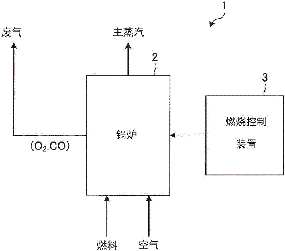
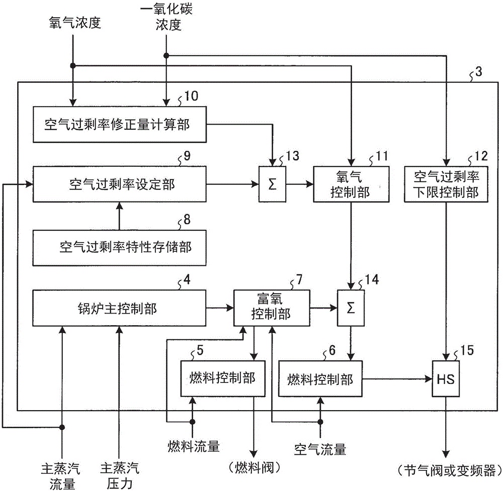
[0036] figure 1 It is a schematic configuration diagram showing a combustion system including the combustion control device according to Embodiment 1 of the present invention. The combustion system 1 shown in this figure includes: a boiler 2 that burns fuel to generate steam, and discharges waste gas (combustion gas) generated by fuel combustion through a discharge channel such as a chimney; and a combustion control device 3 that The device 3 controls the action of the combustion system 1 in a unified manner. The combustion system 1 has various measuring instruments for respectively measuring or setting the following items, namely: fuel flow rate and air flow rate flowing into the boiler 2; main steam flow rate and main steam pressure at the steam outlet of the boiler 2; exhaust gas at the exhaust gas outlet of the boiler 2 temperature; oxygen concentration and carbon monoxide concentration; and the temperature around the boiler 2. In addition, the air flow rate fed into th...

Embodiment approach 2

[0075] Embodiment 2 of the present invention is characterized in that the limit value of carbon monoxide emission (carbon monoxide limit value) that is set is considered according to conditions such as the place where the boiler is installed, and the carbon monoxide emission is kept constant without being affected by the load of the boiler. control. The setting of the carbon monoxide limit value can be realized by inputting the limit value into the combustion control device according to Embodiment 2 in advance by an installation device such as an input device, or by setting (or updating) by communication via a communication network. The configuration of the combustion control device according to the second embodiment is the same as that of the combustion control device 3 described in the first embodiment.

[0076] In Embodiment 2, the following formula (5) which does not include the incomplete combustion factor α is applied as the first heat loss calculation formula for obtain...


PUM


Abstract

The purpose of the invention is to suppress heat loss from exhaust gas easily regardless of boiler type or load. To achieve this purpose, a combustion controlling device comprises: an excess air ratio setting unit that sets, on the basis of a main vapor flow rate from the boiler, an excess air ratio that is the ratio of the air volume to be injected into a boiler to the stoichiometric air volume; an excess air ratio correction volume calculating unit that calculates, on the basis of the oxygen concentration and the carbon monoxide concentration in the exhaust gas from the boiler, a correction volume for the excess air ratio to make the heat loss due to excess air substantially equal to the heat loss due to incomplete combustion; and an oxygen controlling unit that generates, on the basis of the corrected excess air ratio due to the correction volume and the oxygen concentration in the exhaust gas, an air setting correction signal that corrects the set value for the air volume.

Description

technical field [0001] The invention relates to a combustion control device for controlling fuel combustion in a boiler, a combustion control method, a combustion control program and a computer-readable storage medium. Background technique [0002] Currently, in technologies related to the combustion process of boilers, various control methods have been tried in order to realize energy saving and pollution prevention at the same time. For example, there is known a technique for performing optimal control with a low air excess ratio by adjusting the air flow rate by using an air setting signal for setting the air excess ratio characteristic according to the main steam flow rate of the boiler , plus the oxygen (O 2 ) density correction amount (for example, refer to Patent Document 1). The excess air ratio is defined as the ratio of the amount of air actually put into the boiler relative to the theoretical air amount, and is also called the air ratio. Here, the theoretical a...

Claims


Application Information

Patent Timeline
Patent Type & Authority Applications(China)
IPC IPC(8): F23N5/00F23N1/02
CPCF23N1/02F23N5/00F23N5/006F23N2900/05001F23N2225/22
Inventor 稻村康男小泽秀二
Owner FUJI ELECTRIC CO LTD
Why Eureka
Try Eureka