Battery pack

Inactive Publication Date: 2019-01-17
TOYOTA JIDOSHA KK
View PDF1 Cites 5 Cited by
  • Summary
  • Abstract
  • Description
  • Claims
  • Application Information

AI Technical Summary

Benefits of technology

[0013]Heat loss in the bus bar is given by the product of the square of a current flowing in the bus bar and a resistance of the bus bar. Therefore, the heat loss tends to be greater in the region where a higher current flows. On the other hand, since the resistance of the bus bar is inversely proportional to the cross-sectional area of the region, the resistance of the bus bar is reduced by increasing the cross-sectional area of the bus bar. Accordingly, it is possible to reduce the heat loss in the bus bar by increasing the cross-sectional area.
[0014]It may be suggested to reduce the heat loss by uniformly increasing the cross-sectional area of the bus bar. However, in that case, since the cross-sectional areas of the first region and the second region where only relatively small current flows also increase, there is a possibility that the weight of the batte

Problems solved by technology

However, at the same time, with the increase in charge/discharge current, heat loss in the bus bars may also be increased.
However, the increase in the size of the bus bars may increase the weight of the battery pack.
Alternatively, there is a possibility that the fuel consumption of a hybrid

Method used


Image

  • Battery pack
  • Battery pack
  • Battery pack

Examples


Example

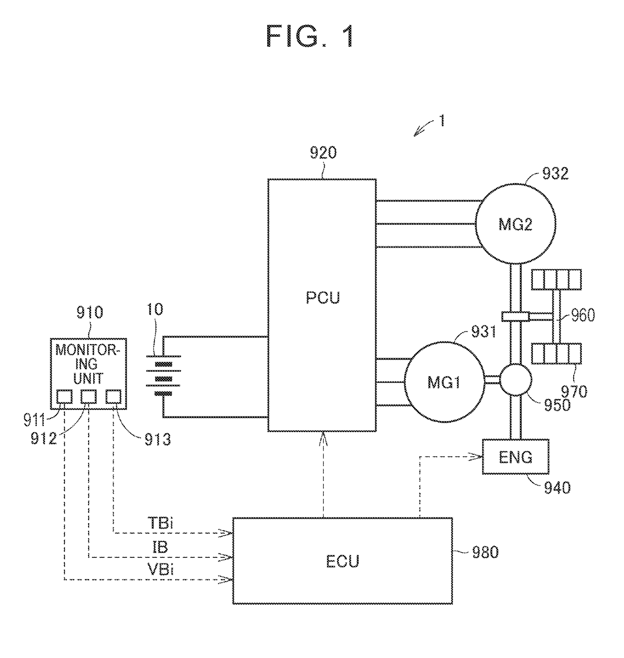
[0028]The first embodiment of the disclosure will be described. First, the overall configuration of an electrically driven vehicle will be described. FIG. 1 is a diagram schematically showing the overall configuration of a vehicle 1 equipped with a battery pack 10 according to the first embodiment. Although a description will typically be given of a case where the vehicle 1 is a hybrid vehicle, a battery pack according to the disclosure is applicable to not only hybrid vehicles but also other vehicles that are respectively equipped with battery packs for travel. The battery pack 10 according to the first embodiment may alternatively be used for another purpose (e.g. for stationary use).

[0029]Referring to FIG. 1, the vehicle 1 includes the battery pack 10, a monitoring unit 910, a power control unit (PCU) 920, motor generators 931, 932, an engine 940, a power split device 950, a drive shaft 960, drive wheels 970, and an electronic control unit (ECU) 980.

[0030]The battery pack 10 incl...

Example

[0074]Next, the second embodiment of the disclosure will be described. In the first embodiment and the first and second modifications thereof, the description has been given of the example in which the cross-sectional area of the bus bar is adjusted by changing the thickness of the bus bar (see FIGS. 5, 6, and 8). However, as will be described below, the cross-sectional area of a bus bar may alternatively be adjusted by changing the width of the bus bar.

[0075]FIG. 9 is a diagram for explaining the configuration of bus bars 61 to 67 in the second embodiment. Referring to FIG. 9, a battery pack 10B differs from the battery pack 10 according to the first embodiment (see FIG. 3) in including the bus bars 62 to 66 instead of the bus bars 32 to 36. The other configuration of the battery pack 10B is the same as the corresponding configuration of the battery pack 10.

[0076]The bus bar 62 connects the cells 101 to 103 in parallel to each other and the cells 104 to 106 in parallel to each othe...


PUM


Abstract

A battery pack includes a bus bar, a first module, and a second module. The bus bar extends in a predetermined direction and includes a first region, a second region and an intermediate region. The first module includes a plurality of cells each including a negative electrode terminal connected to the first region. The second module includes a plurality of cells each including a positive electrode terminal connected to the second region. The negative electrode terminals are arranged in the predetermined direction in the first region. The positive electrode terminals are arranged in the predetermined direction in the second region. In a cross section perpendicular to the predetermined direction, a cross-sectional area of the intermediate region is greater than a cross-sectional area of at least a part of the first region and is greater than a cross-sectional area of at least a part of the second region.

Description

CROSS-REFERENCE TO RELATED APPLICATIONS[0001]The disclosure of Japanese Patent Application No. 2017-136114 filed on Jul. 12, 2017 including the specification, drawings and abstract is incorporated herein by reference in its entirety.BACKGROUND1. Technical Field[0002]The disclosure relates to a battery pack and, more specifically, relates to a battery pack including a bus bar electrically connecting a plurality of cells to each other.2. Description of Related Art[0003]In recent years, electrically driven vehicles equipped with battery packs, such as hybrid vehicles and electric vehicles, have been spreading. Generally, an in-vehicle battery pack includes several ten to several hundred cells. These cells are coupled and electrically connected to each other via bus bars each being a conductor that allows a large current to flow through.[0004]During the charge / discharge of the battery pack, heat loss (Joule heat) is generated in the bus bars. In view of this, a technique has been propos...

Claims


Application Information

Patent Timeline
IPC IPC(8): H01M2/20H01M2/34H01M2/30H01M2/26H01M50/209H01M50/50H01M50/503H01M50/55H01M50/553
CPCH01M2/206H01M2/34H01M2/1077H01M2/26H01R9/2458H01M2/30H01M2220/20H01M50/50H01M50/553H01M50/55H01M50/503H01M50/209Y02E60/10
Inventor YAMANAKA, ATSUSHISUZUKI, YUSUKETSUCHIYA, TAKENORI
Owner TOYOTA JIDOSHA KK
Why Eureka
Try Eureka