Substrate hot processing apparatus and nozzle member

A technology for heat treatment devices and substrates, which is applied in the manufacture of electrical components, semiconductor/solid-state devices, circuits, etc., can solve difficult problems, achieve the effects of suppressing heat loss, suppressing temperature drop, and reducing space

Inactive Publication Date: 2008-10-01
DAINIPPON SCREEN MTG CO LTD
View PDF1 Cites 4 Cited by
  • Summary
  • Abstract
  • Description
  • Claims
  • Application Information

AI Technical Summary

Problems solved by technology

Therefore, it is difficult to miniaturize the substrate heat treatment apparatus along its height direction, and it is difficult to meet the above-mentioned requirements.

Method used


Image

  • Substrate hot processing apparatus and nozzle member
  • Substrate hot processing apparatus and nozzle member
  • Substrate hot processing apparatus and nozzle member

Examples


no. 1 approach

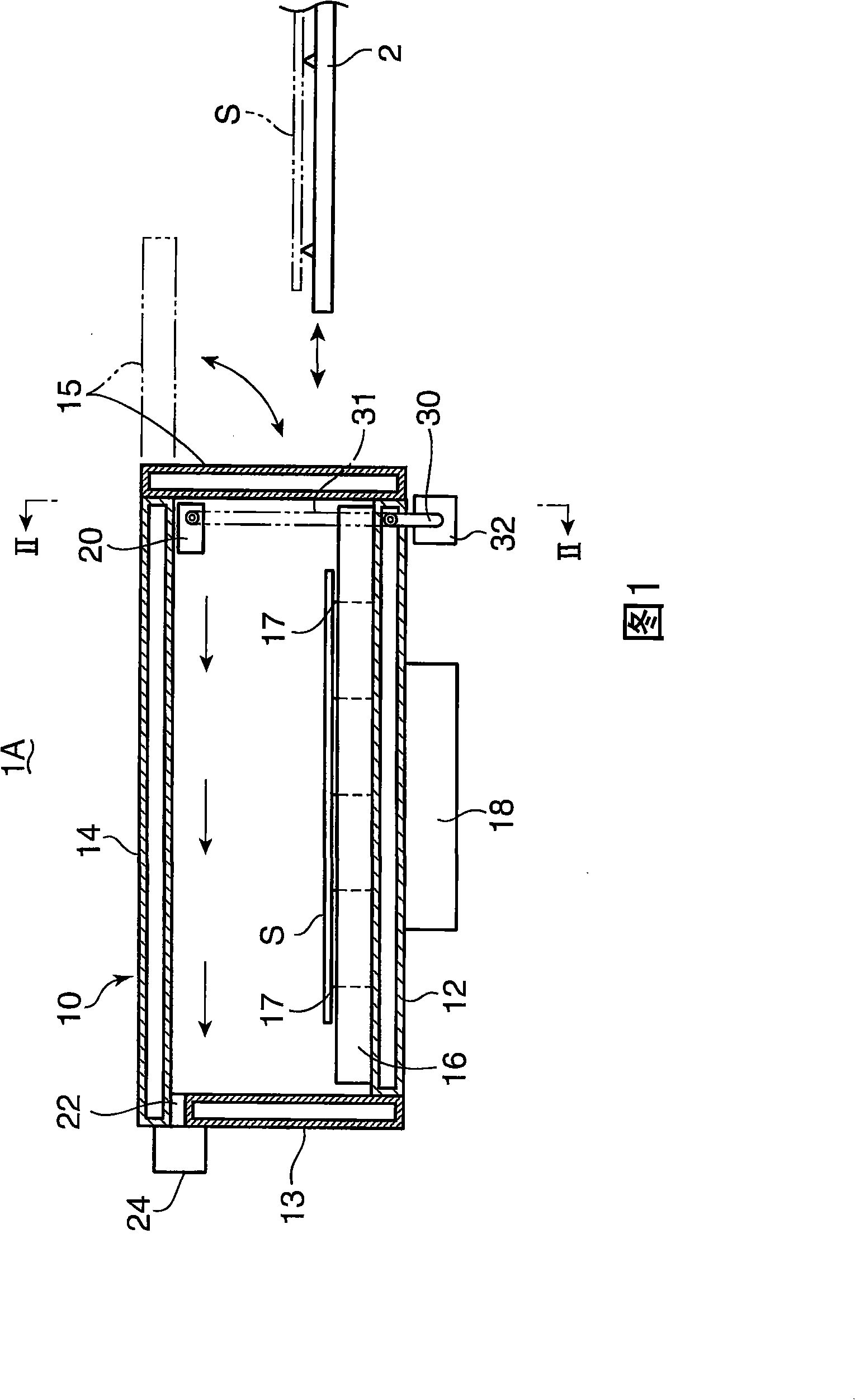
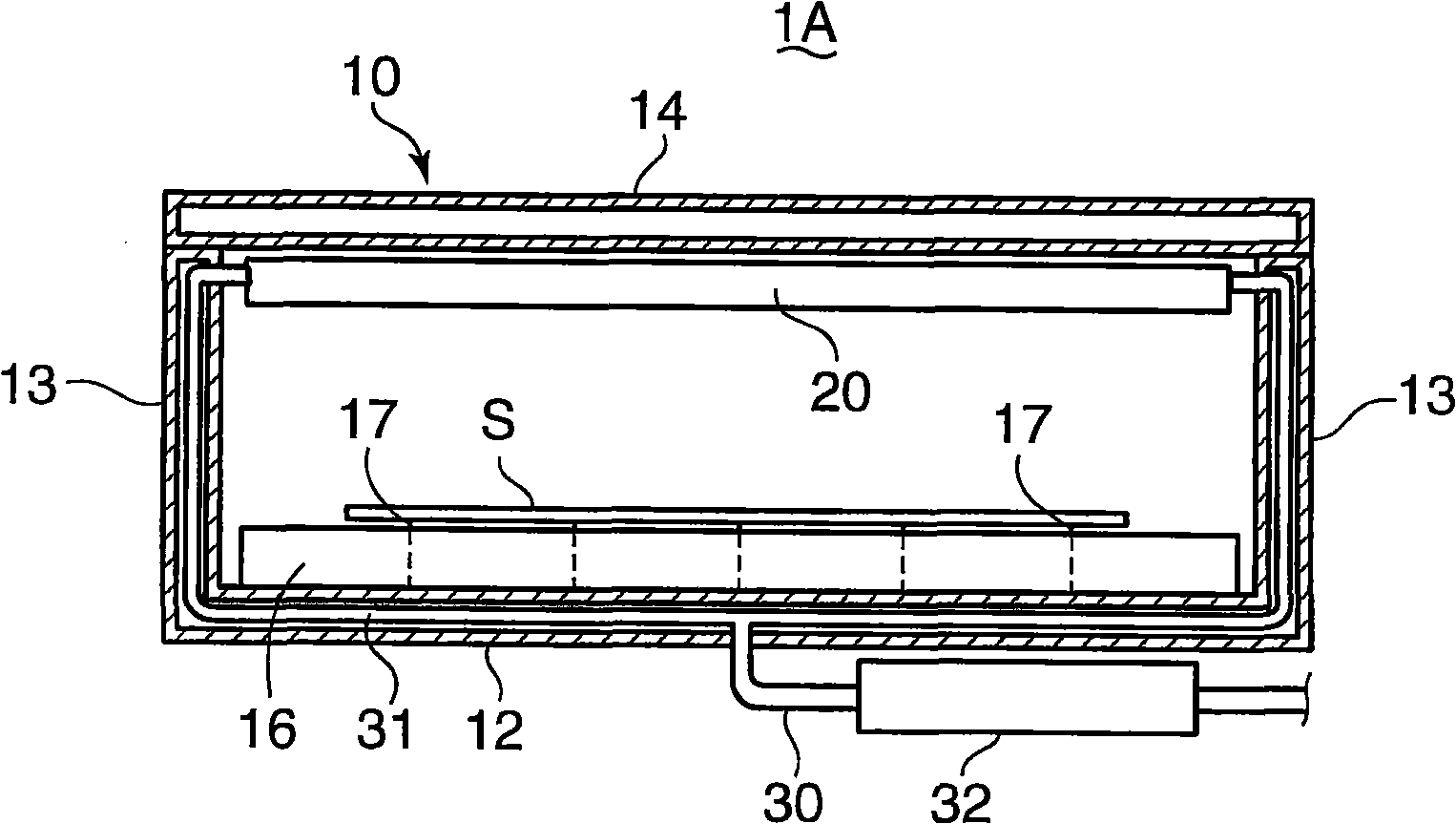
[0081] Figure 1 and figure 2 The first embodiment of the substrate heat treatment apparatus of the present invention is shown in cross-sectional views. As shown in the figure, a substrate heat treatment apparatus 1A (hereinafter simply referred to as “processing apparatus 1A”) has a rectangular cross-sectional housing 10 having a bottom wall 12, side walls 13, and ceiling walls 14 as partition walls. A part of the side wall 13 in the housing 10 serves as a door 15 which opens and closes when the substrate S is carried in and carried out. The side walls 13 and the like constituting the frame body 10 are all provided in a double-wall structure with a space inside, thereby improving the heat insulation effect. In addition, inside the side wall 13 etc., in order to ensure the rigidity, the grid-shaped reinforcement wall is provided, but this is abbreviate|omitted in drawing.

[0082] The inner bottom of the frame body 10 is provided with a heating plate 16 above the bottom wall ...

no. 2 approach

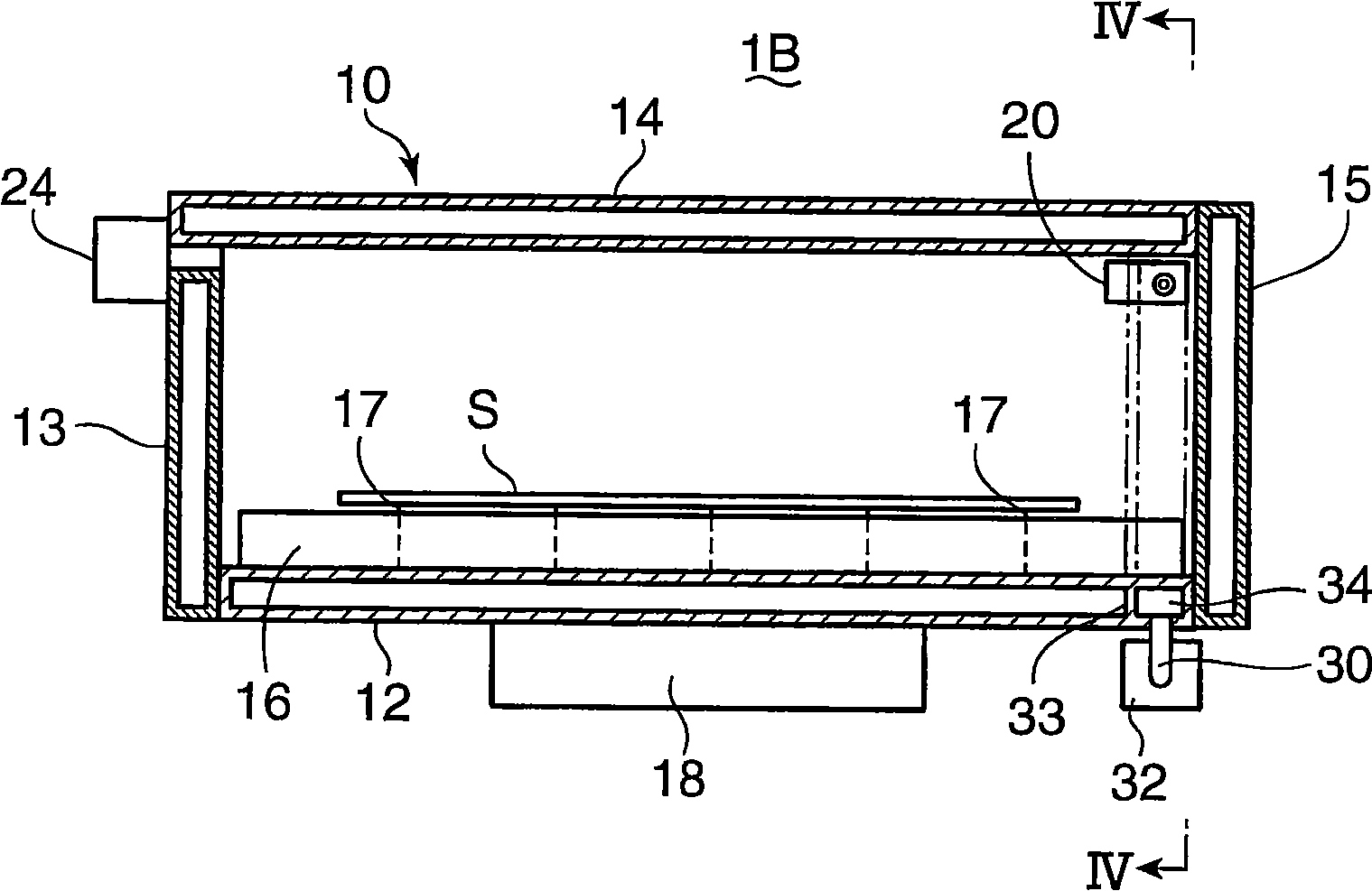
[0093] image 3 and Figure 4 The processing apparatus 1B according to the second embodiment is shown in cross-sectional views, respectively. As shown in this figure, in the processing apparatus 1B of the second embodiment, the configuration of the hot air supply system to the discharge nozzle 20 is different from that of the first embodiment.

[0094] That is, in this embodiment, the internal piping 31 is not provided in the inner space of the bottom wall 12 and the side wall 13 , but the inner space of the bottom wall 12 itself is provided as a mechanism for supplying hot air. Specifically, the inner space of the bottom wall 12 and the side wall 13 is equally divided by the partition wall 33 to communicate from the bottom wall 12 to the side wall 13, and an air flow path 34 is formed, and the air flow path 34 is traversed. Concave sectional shape of the lower part of the heating plate 16 (the sectional concave shape when viewed from the door body 15 side; refer to Figure...

no. 3 approach

[0105] Figure 6 and Figure 7 The processing apparatus 1C of the third embodiment is shown in cross-sectional views, respectively.

[0106] The main difference from the first embodiment is that, in the processing apparatus 1C of the third embodiment, the ejection nozzle 20 is not used, and the ejection mechanism for hot air is integrally provided in the partition wall of the housing 10 . .

[0107] That is, in the interior of the ceiling wall 14 of the housing 10 and in the vicinity of the door body 15, a discharge nozzle 40 (corresponding to the discharge mechanism of the present invention) for discharging hot air into the space in the housing 10 is integrally provided. ). like Figure 8 As shown, the discharge nozzle 40 has a hollow part 41 (corresponding to the introduction flow path of the present invention) and a discharge port 42, and the hot air introduced into the hollow part 41 from the outside of the frame body 10 is passed through the discharge port. 42 to the int...


PUM


Abstract

This invention provides a heat treatment device of base plate and a nozzle component. This device is able to prevent the temperature reduction and supply the hot air with respected temperature to a frame in more suitable way. The heat treatment device (1A) of base plate includes a frame (10) surrounding a heating plate (16) and a supply mechanism of hot air which is provided with a jet nozzle (20) mounted in the frame; the supply mechanism of hot air discharges the hot air through a vent (22) mounted at a side wall (13) of the frame (10) as well as supplies the hot air along the upper of the frame (10) internal. The supply mechanism of hot air includes a supply pipe (30) and an internal pipe (31); the supply pipe (30) is provided with a heater (32); the internal pipe (31) supplies the heated hot air to said jet nozzle (20) through the internal of the side wall (13) of the frame (31) and so on.

Description

technical field [0001] The present invention relates to substrate heat treatment for heat-treating semiconductor substrates, glass substrates for liquid crystal display devices, glass substrates for plasma display devices, glass substrates for photomasks, glass substrates for optical discs, etc. (hereinafter referred to as "substrates") Device and nozzle parts employed in the device. Background technique [0002] In the prior art, as such a substrate heat treatment device, there is a device in which a heating plate and substrate support pins that pass through the heating plate and move forward and backward are provided in the inner space of the frame, the substrate is supported by the support pins, and The substrate is heat-treated with heat generated by a hot plate. [0003] In this substrate heat treatment apparatus, for example, when heat-treating a substrate coated with a resist solution, components of some types of resist solution sublimate, and the sublimated substanc...

Claims


Application Information

Patent Timeline
Patent Type & Authority Applications(China)
IPC IPC(8): H01L21/00
Inventor 中根慎悟
Owner DAINIPPON SCREEN MTG CO LTD
Why Eureka
Try Eureka