Air-conditioner for vehicle

a technology for air conditioners and vehicles, applied in the field of air conditioners, can solve the problems of not being able to prevent and achieve the effect of reducing the freezing of evaporators

Inactive Publication Date: 2007-11-08
DENSO CORP
View PDF2 Cites 22 Cited by
  • Summary
  • Abstract
  • Description
  • Claims
  • Application Information

AI Technical Summary

Benefits of technology

[0015]Accordingly, freezing of the evaporator can be reduced.

Problems solved by technology

That is, the above-described control is a feedback control, which may not be able to prevent the freezing of the evaporator.

Method used


Image

  • Air-conditioner for vehicle
  • Air-conditioner for vehicle
  • Air-conditioner for vehicle

Examples


first embodiment

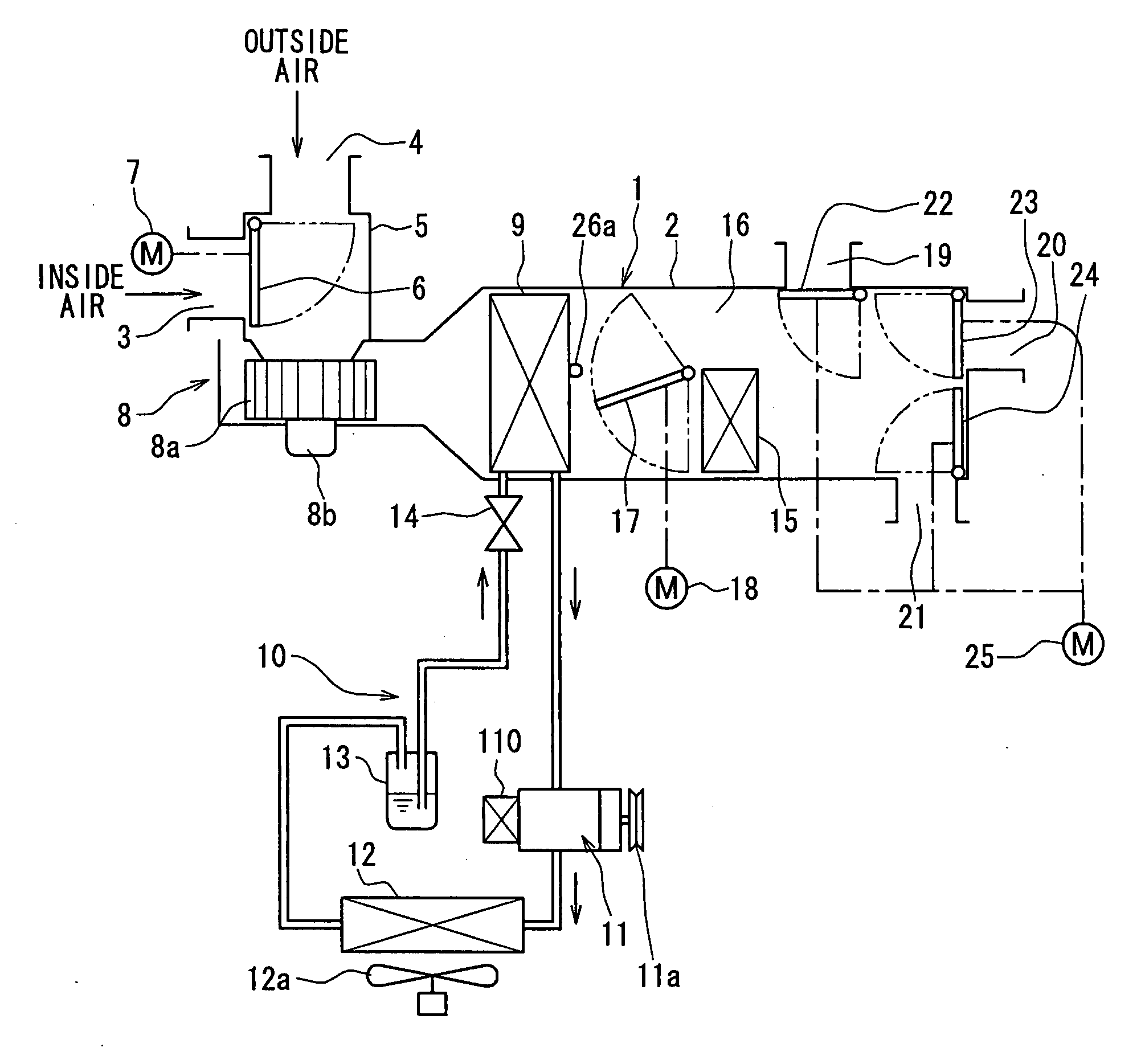
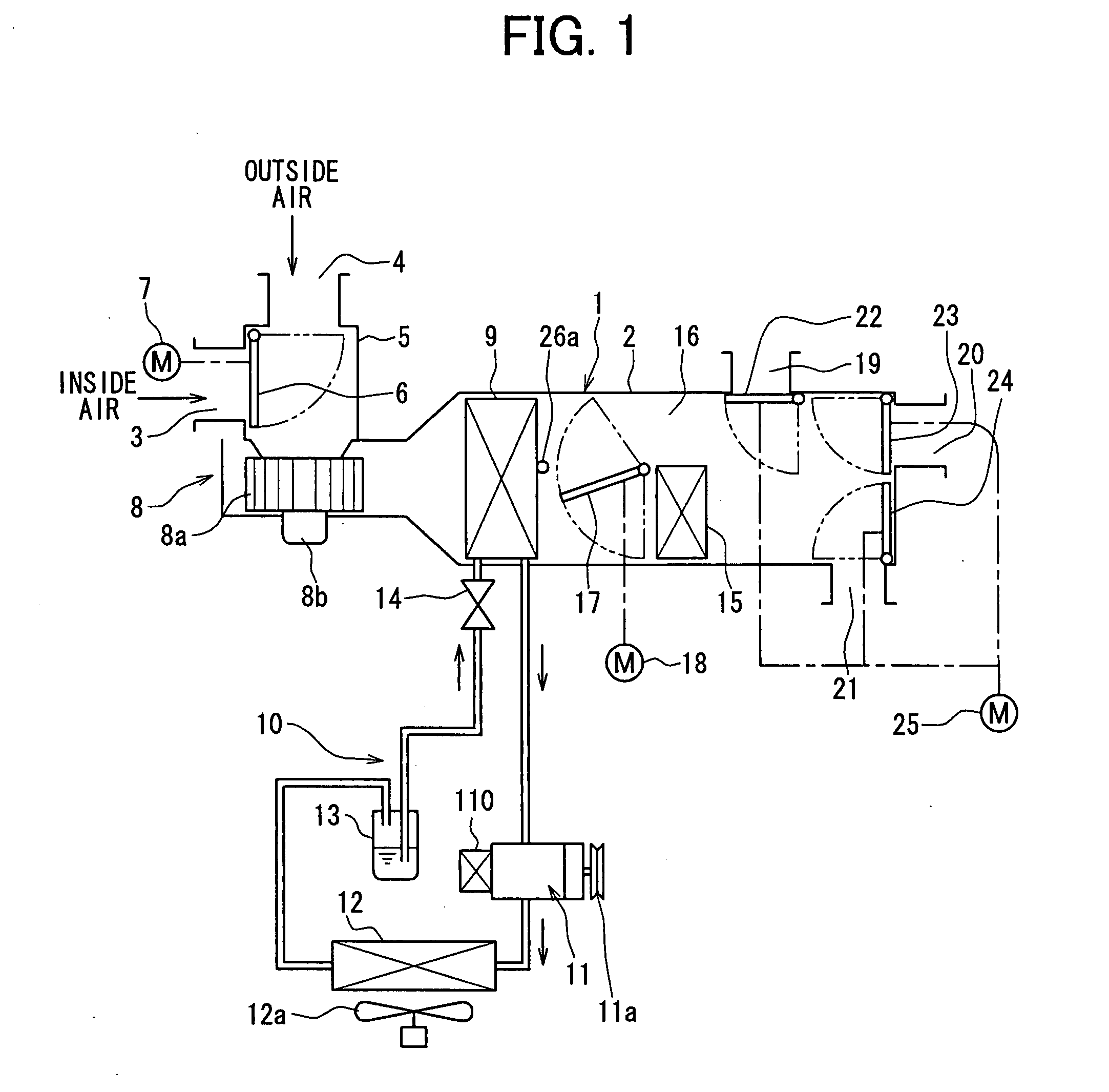
[0030]As shown in FIG. 1, an air-conditioner includes an air-conditioning unit 1 and a refrigeration cycle device 10, and is typically used for a vehicle. An evaporator 9 is disposed in the air-conditioning unit 1. Refrigerant for cooling air sent into a vehicle compartment flows in the evaporator 9 and the refrigeration cycle device 10. When the air-conditioning unit 1 is disposed in an instrument panel at a front part of the vehicle, the air-conditioning unit 1 is used for conditioning air adjacent to a front seat in the vehicle compartment. When the air-conditioning unit 1 is disposed in a trunk or a side-trim at a rear part of the vehicle, the air-conditioning unit 1 is used for conditioning air adjacent to a rear seat in the vehicle compartment.

[0031]The air-conditioning unit 1 has a case 2, and the case 2 has an air passage, through which air is sent toward an occupant in the vehicle compartment. An intake air switching box 5 is disposed at an upstream part of the air passage,...

second embodiment

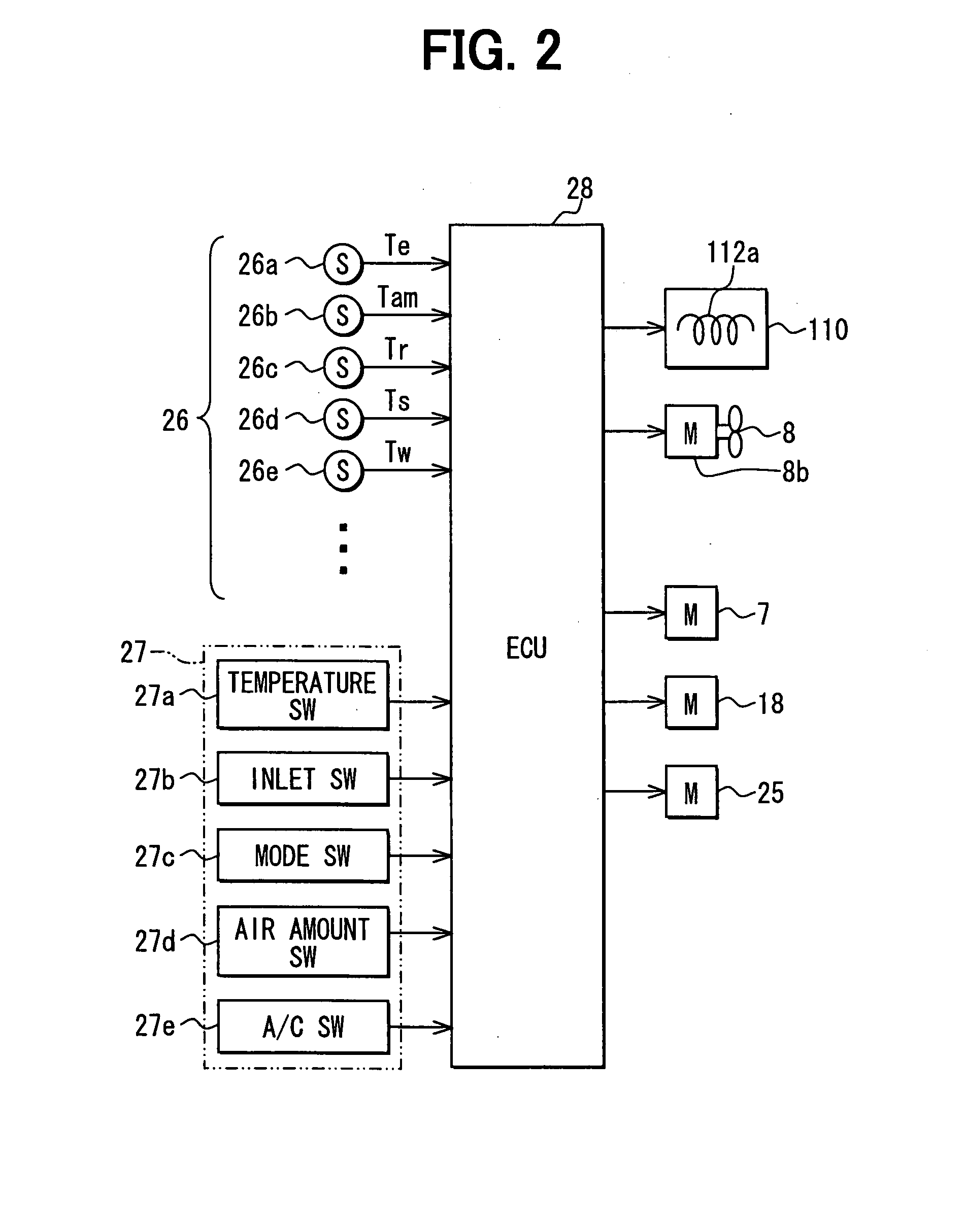
[0066]A control of the compressor 11 in a second embodiment will be described with reference to FIGS. 7 and 8. When the air-conditioning switch 27e is turned on, the ECU 28 performs a subroutine A shown in FIG. 8 (S150 in FIG. 7).

[0067]As shown in FIG. 8, in the subroutine A, the ECU 28 performs a treatment for detecting a revolution number Ne(rpm) of the vehicle engine (S151). Next, when the detected revolution number Ne is equal to or larger than a predetermined value N1, the ECU 28 applies the detected revolution number Ne into a control characteristic map of S152, and calculates an evaporator surface temperature TEOA. The predetermined value N1 is a revolution number capable of causing the freezing of the evaporator 9, because the compressor 11 has a high capacity for compressing refrigerant. The predetermined value N1 is determined based on experiments, and memorized in the ECU 28 in advance.

[0068]When the detected revolution number Ne is between N1 and N2, the evaporator surfa...

third embodiment

[0077]A control of the compressor 11 in a third embodiment will be described with reference to FIGS. 9 and 10. When the air-conditioning switch 27e is turned on, the ECU 28 performs a subroutine B shown in FIG. 10 (S154 in FIG. 9).

[0078]As shown in FIG. 10, in the subroutine B, the ECU 28 performs a treatment for detecting an outside air temperature TAM(° C.) through the outside air temperature sensor 26b (S155). Next, when the detected outside air temperature TAM is equal to or smaller than a predetermined value T2, the ECU 28 applies the detected outside air temperature TAM into a control characteristic map of S156, and calculates an evaporator surface temperature TEOB. The predetermined value T2 is an outside air temperature capable of causing the freezing of the evaporator 9, because the condenser 12 has a high cooling capacity. The predetermined value T2 is determined based on experiments, and memorized in the ECU 28 in advance.

[0079]When the detected outside air temperature TA...


PUM


Abstract

An air-conditioner includes a refrigeration cycle device having an evaporator for evaporating refrigerant discharged from a compressor to cool air to be sent into a vehicle compartment. A controller turns on the compressor when a surface temperature of the evaporator or a downstream temperature of air at a downstream side of the evaporator is equal to or larger than a first predetermined value. The controller turns off the compressor when a changing rate of the surface temperature or a changing rate of the downstream temperature is equal to or larger than a second predetermined value. The controller turns on the compressor again when the surface temperature or the downstream temperature becomes equal to or larger than a third predetermined value, which is larger than the first predetermined value.

Description

CROSS REFERENCE TO RELATED APPLICATION[0001]This application is based on Japanese Patent Application No. 2006-129456 filed on May 8, 2006, the disclosure of which is incorporated herein by reference in its entirety.BACKGROUND OF THE INVENTION[0002]1. Field of the Invention[0003]The present invention relates to an air-conditioner, which is typically used in a vehicle.[0004]2. Description of Related Art[0005]JP-A-7-246832 discloses an air-conditioner for a vehicle. A duct sensor detects a temperature of a compressor, or a temperature of air at a downstream side of an evaporator, and the detected temperature is defined as a recognition temperature. The air-conditioner detects the lowest value among the recognition temperatures, and calculates deviation of the lowest value relative to a determination temperature for determining a start or stop of the compressor. When the calculated deviation is equal to or larger than a predetermined value, the determination temperature is increased. Th...

Claims


Application Information

Patent Timeline
Patent Type & Authority Applications(United States)
IPC IPC(8): F25D29/00
CPCB60H1/00735B60H1/321B60H2001/3261B60H2001/3263B60H2001/327F25B2700/21173F25B2500/19F25B2600/0251F25B2700/171F25B2700/2117F25B49/022
Inventor HAYASHI, HIROYUKI
Owner DENSO CORP
Why Eureka
Try Eureka