High-speed thermal circulation air curtain apparatus for tunnel portals

A technology of thermal circulation and circulating air duct, applied in the field of fixed buildings, can solve problems such as energy waste affecting driving safety, and achieve the effects of reducing freezing phenomenon, driving safety, and reducing heat demand

Active Publication Date: 2009-07-08
SHANGHAI TUNNEL ENGINEERING RAILWAY TRANSPORTATION DESIGN INSTITUTE
View PDF0 Cites 4 Cited by
  • Summary
  • Abstract
  • Description
  • Claims
  • Application Information

AI Technical Summary

Problems solved by technology

At the same time, under normal circumstances, the internal temperature of the subway is kept above 5°C. On the interface between cold and heat at the entrance of the tunnel, the airflow frequently enters and exits, causing the tunnel entrance to freeze, which affects driving safety and wastes energy.
[0004] In my country, due to the fact that there are few large cities in the high-latitude alpine zone, the subway systems in Shenyang, Changchun, Harbin and other places are still planning or under construction, and there is no existing technology to solve the problem in a targeted manner.

Method used


Image

  • High-speed thermal circulation air curtain apparatus for tunnel portals
  • High-speed thermal circulation air curtain apparatus for tunnel portals

Examples


Embodiment 1

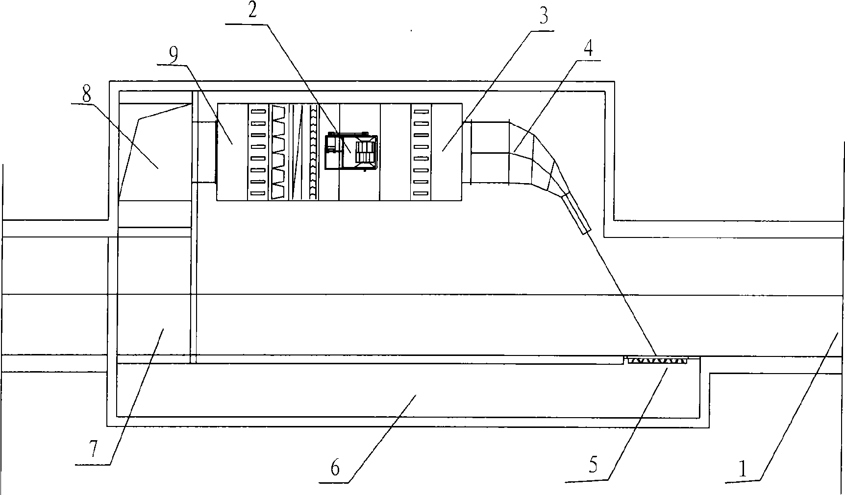
[0014] Embodiment one: if figure 1 As shown, this embodiment includes a tunnel entrance 1, an air handling unit 2, an air handling unit outlet 3, a high-speed nozzle 4, a circulating air duct inlet 5, a circulating air duct 6, a rail passing air duct 7, a circulation chamber 8, an air Air inlet 9 of the processing unit. A set of air handling unit 2 is installed on the side of the tunnel entrance 1 near the station. The air heated and pressurized by the air handling unit sprays out the hot air curtain at high speed through the air outlet 3 and the high-speed nozzle 4 connected to the air outlet. On the other side of the tunnel The circulation air duct 6 is set at the flow direction of the hot air curtain, and the hot air curtain flows back to the circulation chamber 8 connected to the air inlet 9 of the air handling unit through the circulation air duct 6 and the rail passage 7 in turn, and then enters the air handling unit to complete the circulation of the hot air curtain . ...

Embodiment 2

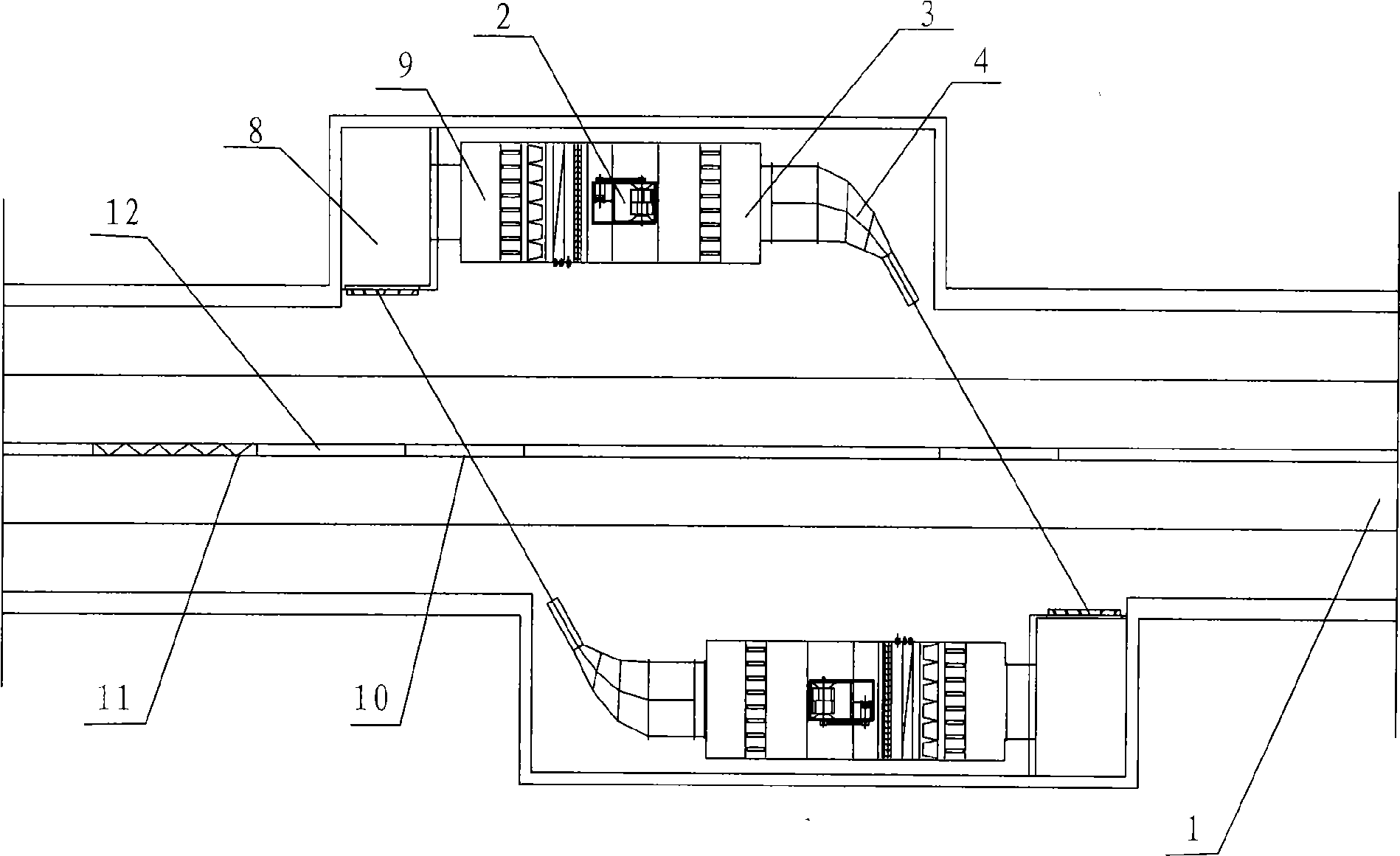
[0017] Embodiment two: if figure 2 As shown, this embodiment includes a tunnel entrance 1, an air handling unit 2, an air handling unit air outlet 3, a high-speed nozzle 4, a circulation chamber 8, an air handling unit air inlet 9, a channel 10, a circuitous air duct 11, and a tunnel partition wall 12. A group of air handling units 2, high-speed nozzles 4 and circulation chamber 8 are installed on both sides of the tunnel, and two hot air curtains are generated at the tunnel entrance 1, and the hot air curtain generated on one side is blown to the circulation chamber on the other side to form a circulating hot air screen. The wind speed of the hot air curtain ejected from the high-speed nozzle 4 must also be no less than 20 m / s, and the installation angle of the high-speed nozzle 4 must ensure that the hot air curtain flows to the circulation chamber on the other side.

[0018] When it is a parallel double-hole tunnel running on two lines, a channel 10 is provided on the tu...


PUM


Abstract

The invention relates to fixed buildings, in particular to a tunnel portal high speed heat cycle wind curtain device which is suitable for track traffic main lines of high latitude and cold areas and inlet and outlet line portals. The device is provided with a hot air curtain which is injected at a high speed at the tunnel portal and forms a thick air curtain wall at the tunnel portal so as to stop the intrusion of severe cold air outside a tunnel, and reduce heat exchange. When the tunnel is a parallel double-portal tunnel, a communication channel and a bypass channel are added in the tunnel partition wall so as to effectively lead the piston wind of a train. At the same time, a cycle wind channel, a track passing channel, a ventilation chamber, and the like are arranged so as to achieve the cycle of hot air, effectively reduce heat requirements of adjacent stations, stabilize the station temperature, and reduce freezing phenomenon generated by cold and heat intersection of the portal, thereby making traffic safe.

Description

technical field [0001] The invention relates to fixed buildings, in particular to a high-speed heat-circulating air curtain device for tunnel entrances suitable for the entrances of rail transit main lines and entry and exit lines in high-latitude alpine regions. Background technique [0002] In the subway system, when the underground section extends from the underground to the ground, due to the influence of the piston wind of the train running, the train enters and exits the tunnel entrance, or due to the influence of the train running in the adjacent tunnel, there is an airflow exchange between the tunnel entrance and the outdoor air. The highest instantaneous airflow in the tunnel where the train runs directly can exceed 15m / s, and the wind speed can reach several meters / second due to the influence of adjacent sections. [0003] In high-latitude and high-cold regions like Harbin, when the outdoor temperature is extremely low (for example, the winter heating temperature i...

Claims


Application Information

Patent Timeline
Patent Type & Authority Applications(China)
IPC IPC(8): E21F1/14F24F9/00
Inventor 郑晋丽刘锐人阎正才姜益强刘文胜
Owner SHANGHAI TUNNEL ENGINEERING RAILWAY TRANSPORTATION DESIGN INSTITUTE
Why Eureka
Try Eureka