Automatic system for abrasive hardfacing

a technology of automatic system and hardfacing, which is applied in the field of metalworking process, can solve the problems of undesirable amount of abrasives ending up on the floor, affecting the quality of abrasives, and so as to reduce the waste of wear resistant feed particles, reduce and reduce the effect of reducing the chance of nucleation

Active Publication Date: 2015-09-24
VERMEER MFG CO
View PDF10 Cites 4 Cited by
  • Summary
  • Abstract
  • Description
  • Claims
  • Application Information

AI Technical Summary

Benefits of technology

[0006]In various aspects, the invention provides apparatus and systems and methods for application of hardfacing materials including carbide particles. The apparatus, systems and methods of the invention can allow for production of carbide-containing hardfacings with good incorporation and distribution of wear resistant particles within the hardfacing. Embodiments of the present apparatus, systems and methods in which oscillatory movement of the weld pool is induced may enhance such factors as mixing / distribution of the carbide / particulate material within the weld pool and a reduced opportunity of nucleation of secondary phase materials proximate the added hardfacing material, which can produce surprising beneficial results within the resultant hardfacing microstructure. The apparatus, systems and methods provided can also reduce waste of wear resistant feed particles as compared to conventional apparatus, systems and methods.
[0007]In one aspect of the disclosure, an arc welding system includes an arc welding torch, a particulate delivery system, and a movable workpiece holder. In embodiments the arc welding torch is stationary with respect to the workpiece or the speed of movement of the tip of the torch is less than that of the workpiece during a given arc welding pass. It is demonstrated herein that movement of the workpiece while keeping the welding torch and particulate delivery system stationary during a welding pass can increase the number of particles incorporated into the weld pool as compared to a welding pass in which the workpiece is held stationary and the welding torch moved. In an embodiment, oscillatory movement of the workpiece during the welding pass is selected to enhance mixing and / or interrupt the formation of nucleation sites within the weld pool, which essentially slows freezing of the pool. Since there is very short period available (e.g. a fraction of a second) to accommodate the particulate into the weld pool before the pool becomes too viscous and eventually solidifies, the processes of the invention can help maximize the time available to get the desired level of carbide impregnation. In addition, movement of the workpiece during the welding pass can reduce dissolution and / or formation of second phase(s) at the interface of tungsten carbide particles.
[0008]In a further embodiment, oscillatory movement of the workpiece while keeping the welding torch stationary or moving the tip of the welding torch at a relatively low speed allows use of high speeds in the welding pass direction. For example, a process speed of about 10-40 in / min, 15-30 in / min, 20-30 in / min or 20-40 in / min can be obtained by moving the workpiece via the moving workpiece holder and using an oscillating motion with an ultimate “forward” motion in the welding pass direction. The efficiencies in getting carbide into the puddle associated with processes of the present invention can produce desirable hardfacings while permitting faster process speeds than those speeds (e.g., 10-12 in / min or less) typically associated with the use of a moving gun / drop tube and stationary sample. In another aspect of the invention, relatively high weld amperages and wire feed speeds are be used in conjunction with relatively high lineal weld process speeds. In an embodiment, the incorporation of relatively large amounts of carbide particles has a greater cooling effect on the weld puddle, which allows use of the relatively high weld amperages and wire feed speeds.

Problems solved by technology

First, harmonics in the delivery tube cause a sloshing effect therein that can cause the delivery tube 514 to wear out fairly quickly.
Secondly, the same harmonics / motion makes it much more difficult to control the placement of the carbide / abrasive within the weld puddle and, likewise, to achieve even distribution of the abrasive throughout the finished weld bead.
Finally, because of the difficulty in controlling the placement of the abrasive in the desired location, an undesirable amount of the abrasive can end up on floor and / or otherwise going to waste.

Method used


Image

  • Automatic system for abrasive hardfacing
  • Automatic system for abrasive hardfacing
  • Automatic system for abrasive hardfacing

Examples


example 1

Comparison of Hardfacing Samples with Tungsten Carbide Particles with Stationary Sample and Moving Sample

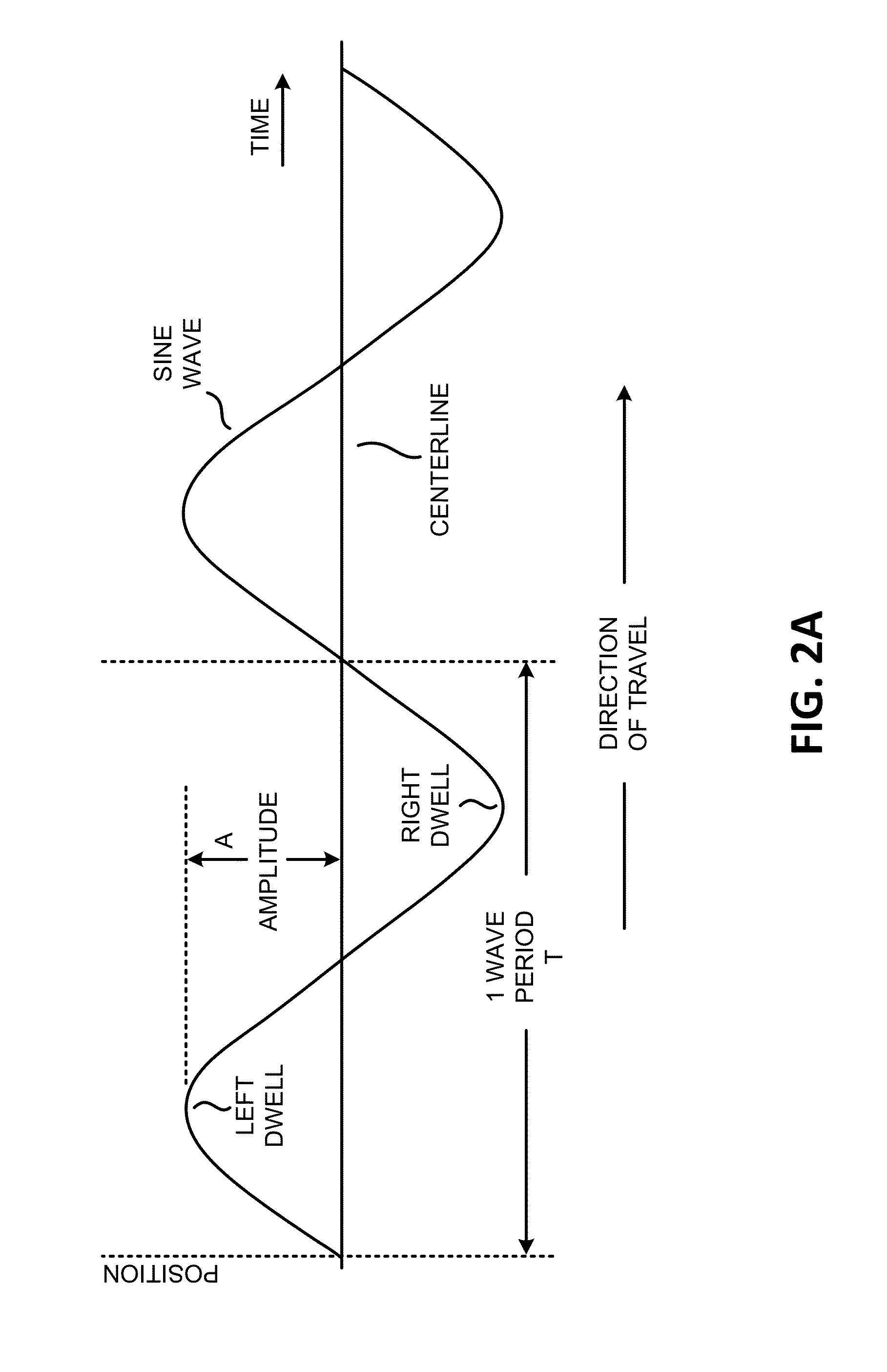
[0125]FIGS. 10A and 10B compare hardfacing samples with made with a lateral travel speed of 12 inches per minute and a weaving pattern. The feed wire was mild steel and the carbide particles were tungsten carbide particles (initial size 12-24 mesh). The wire feed speed and the voltage were approximately the same for both samples (350-375 inches / minute and 26 V). The carbide drop rate was 5 g / sec for both samples. FIG. 10A illustrates a hardfacing applied to a stationary sample with a moving arc welding head at an oscillation frequency of 4 Hz and an amplitude of 1 mm. The measured area fraction of carbide particles was 16%, the top height measurement labeled 2 was 0.1364 inches, the bottom height measurement labeled 3 was 0.0944 inches, and the width measurement was 0.5748 inches. FIG. 10B illustrates a hardfacing applied to a moving sample with a stationary arc welding head at a...

example 2

Comparison of Hardfacing Samples with Silicon Carbide Particles with Stationary Sample and Moving Sample

[0128]FIG. 13A shows a cross-sectional micrograph (50× magnification) of a hardfacing made with silicon carbide particles, a moving workpiece and a stationary weld gun. The percentage of hardfacing area with hardness 60 HRC and above is 100%.

[0129]FIG. 13B shows a cross-sectional micrograph (50× magnification) of a hardfacing made with silicon carbide particles, a stationary workpiece and a moving weld gun. The percentage of hardfacing area with hardness 50 HRC and below is 100%. The numerical labels indicate hardness values (HRC).

[0130]FIG. 14 shows another cross-sectional micrograph (50× magnification) of the same hardfacing as in FIG. 13A, made with a stationary workpiece and a moving weld gun. The percentage of hardfacing area with hardness 50 HRC and below is 100%. The numerical labels indicate hardness values (HRC).


PUM

PropertyMeasurementUnit
frequencyaaaaaaaaaa
frequencyaaaaaaaaaa
volume fractionaaaaaaaaaa

Abstract

Arc welding systems, apparatus and methods are for hardfacing are provided, including particle feeding apparatus. In one aspect the workpiece is moved in an oscillatory fashion while keeping the welding torch and the particulate delivery system stationary during at least a portion of welding pass. The welding torch and particulate delivery system may also be moved in a non-oscillatory fashion. Process speeds of about 18-30 in / min can be obtained with carbide incorporation of greater than 30% and uniform distribution.

Description

CROSS-REFERENCE TO RELATED APPLICATIONS[0001]This application is a continuation-in-part of International Application PCT / US15 / 21327, filed Mar. 18, 2015, which claims the benefit of U.S. Provisional Application Nos. 61 / 955,078, filed Mar. 18, 2014, 62 / 077,142, filed Nov. 7, 2014 and 62 / 088,278, filed Dec. 5, 2014, all of which are hereby incorporated by reference in their entireties.BACKGROUND OF THE INVENTION[0002]Hardfacing is a metalworking process where harder or tougher material is applied to a base metal, typically by an arc welding process. One common technique for achieving hardfacing is to form a weld puddle on an area to be hardfaced and concurrently feed a particulate with favorable wear and / or abrasive characteristics into the weld puddle, effectively creating a surface composite upon solidification.[0003]Some current robotics-based hardfacing systems employ a workpiece fixed in a given location, with a movable arc welding unit and a concurrently-operating feed system fo...

Claims


Application Information

Patent Timeline
Patent Type & Authority Applications(United States)
IPC IPC(8): B23K9/04B23K9/32
CPCB23K9/324B23K9/04
Inventor BEARY, SCOTT W.PROFFITT, MICHAEL J.WEINBERG, CLINT A.MUCHTAR, WANTILANDON, DAVIDJOHNSON, BJORN
Owner VERMEER MFG CO
Why Eureka
Try Eureka