
System and Method for Estimating Formation Supercharge Pressure

a formation supercharge and pressure technology, applied in the field of formation supercharge pressure estimation, can solve the problems of not necessarily eliminating the supercharge effect, the method is generally not practical,

Inactive Publication Date: 2007-11-08
BAKER HUGHES INC
View PDF7 Cites 15 Cited by
  • Summary
  • Abstract
  • Description
  • Claims
  • Application Information

AI Technical Summary

Benefits of technology

[0009]Examples of the more important features of the method and apparatus for estimating formation pressure have been summarized rather broadly in order that the detailed description thereof that follows may be

Problems solved by technology

During overbalanced drilling, the drilling mud invades or penetrates the permeable rocks (formation) penetrated by the well.
Such a method is generally not practical, especially in logging-while-drilling (LWD) environments.
If the mudcake is leaky, even pumping for a long time may not necessarily eliminate the supercharging effect.

Method used


Image

  • System and Method for Estimating Formation Supercharge Pressure
  • System and Method for Estimating Formation Supercharge Pressure
  • System and Method for Estimating Formation Supercharge Pressure

Examples


case 1

Field Case 1

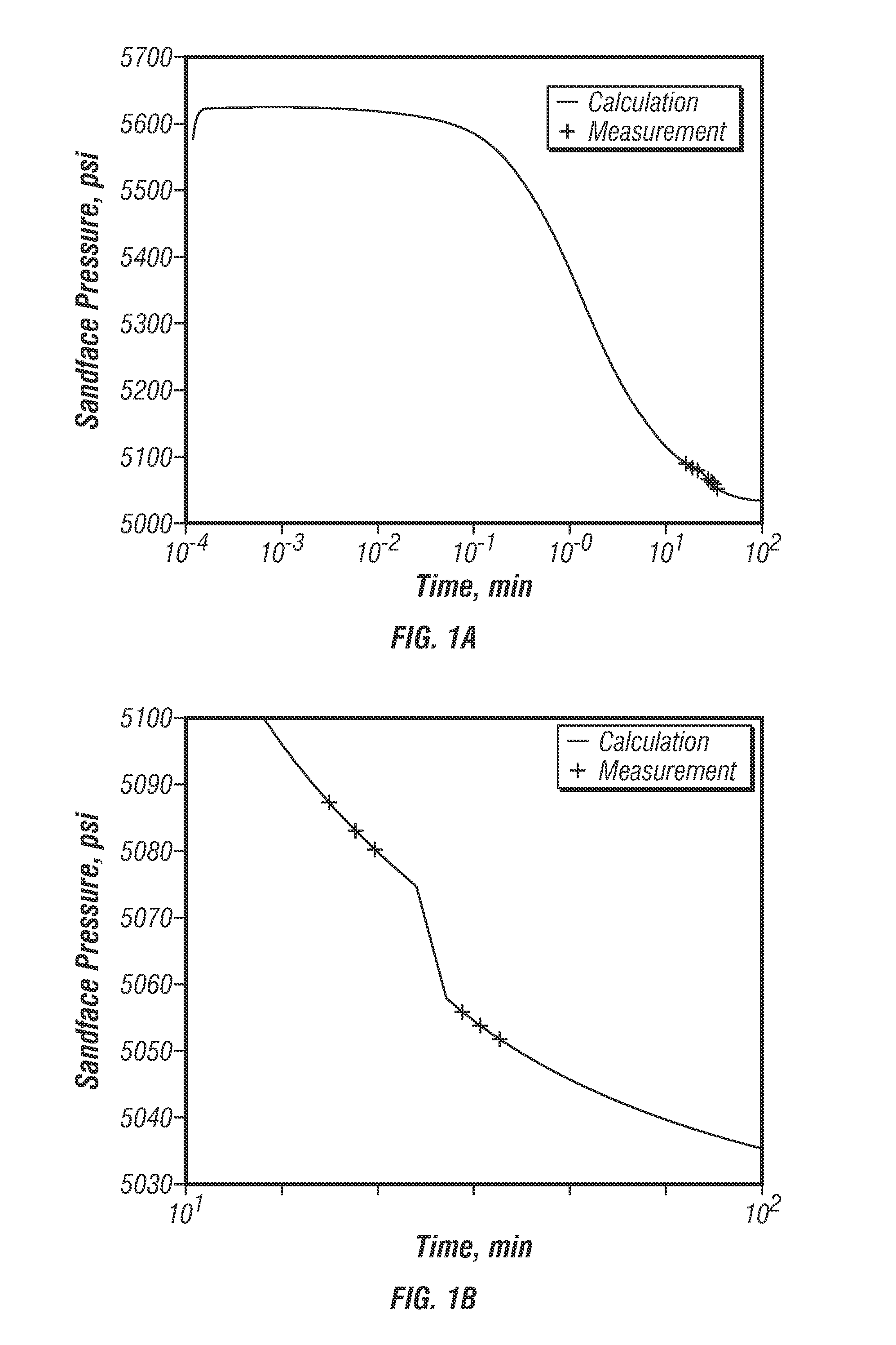
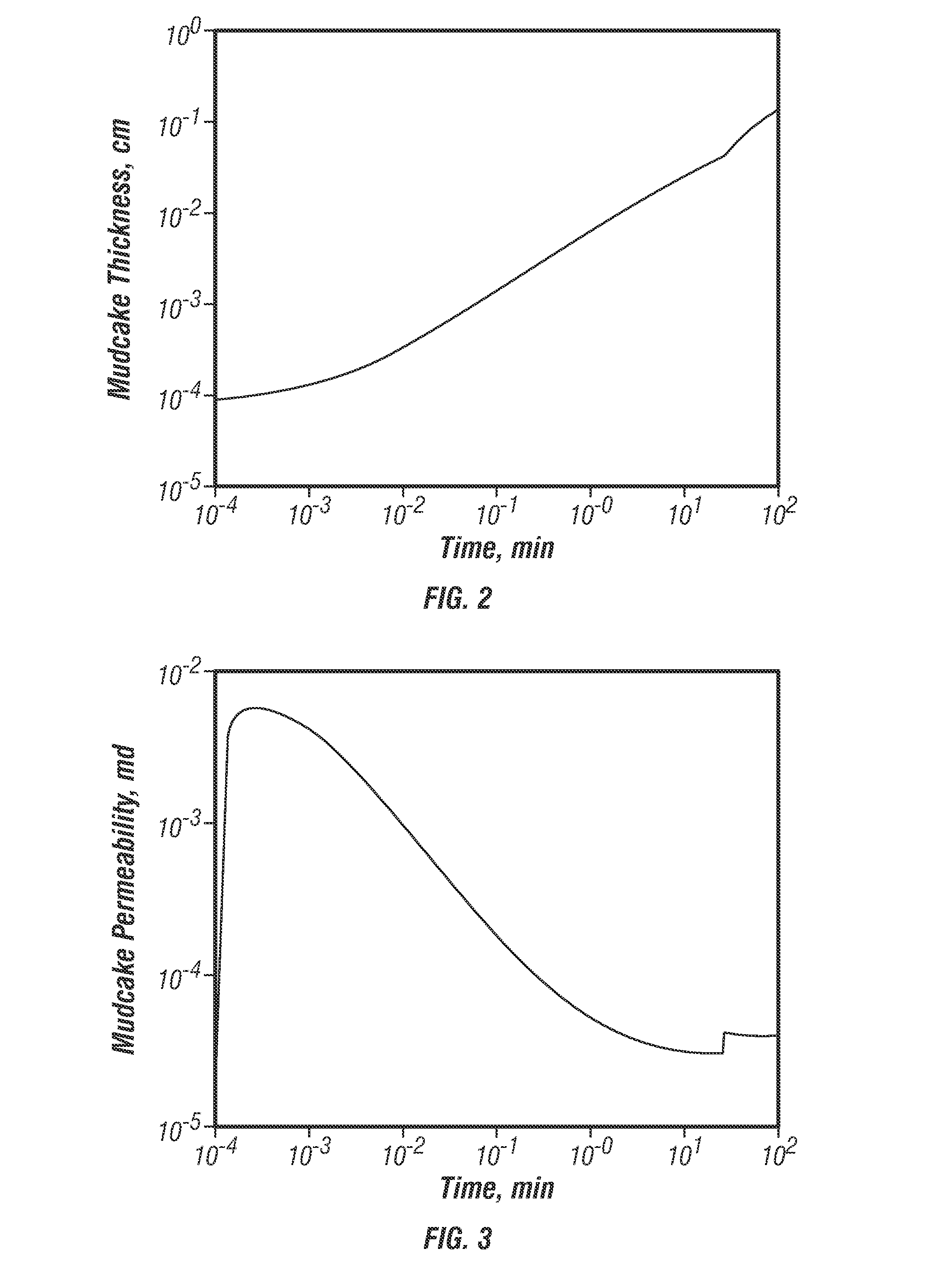
[0036]In the Field Case 1, two scenarios are described. In the first scenario (Scenario 1-A), the first test measurements were made 18 minutes after drilling, using a formation test tool, such as described in reference to FIG. 15 or a tool used during drilling of the well. This is a repeat pressure test case. The first scenario assumes that the actual time-since-drilled is unknown and an arbitrary time-since-drilled (t=18 minutes) is assigned to the time when the build-up pressure of the first test was measured.

[0037]Two sets of three repeat pressure tests were conducted at different hydrostatic pressures. The first set of pressure tests was conducted under 5626 psi hydrostatic pressure, then the hydrostatic pressure was lowered to 5417 psi at t equals 26 minutes, and then a second set of repeat pressure tests was conducted. The measured build-up pressures for the first set of repeat tests were 5087.72, 5083.63, and 5080.66 psi respectively, and the build-up pressures fo...

case 2

Field Case 2

[0044]The second field case relates to a time-lapse repeat testing case for well using a formation testing tool. The testing location depth was at 18,400 ft. Two sets of repeat tests (six tests) were conducted during drilling, and one set of repeat tests (three tests) was re-logged after three days. The three day time-lapse pressure difference was 14 psi due to dissipation of the supercharge pressure.

[0045]The first set of repeat pressure tests was conducted under 4026.7 psi of hydrostatic pressure, then the hydrostatic pressure was dropped to 4023.8 psi, and another three repeat pressure tests were conducted. The measured build-up pressures for the first set of repeat tests were 2850.3, 2849.9, and 2850.2 psi, respectively; and the build-up pressures for the second set of repeat tests were 2843.1, 2841.7, and 2841.2 psi, respectively. This decreasing trend of build-up pressure in repeat tests is believed to be a supercharging effect.

[0046]The objective function uses the...

example 1

Pmh=5626.11 psi, Pss(t1)=5087.72 psi, Pss(t2)=5083.63 psi, and Pss(t3)=5080.66 psi, (t2−t1)=110 second, (t3−t2)=96 second, a and b are calculated to be 0.992461 and 0.987057. C=0.07808, G=0.001056, Pi is estimated to be 5045.68 psi.


PUM


Abstract

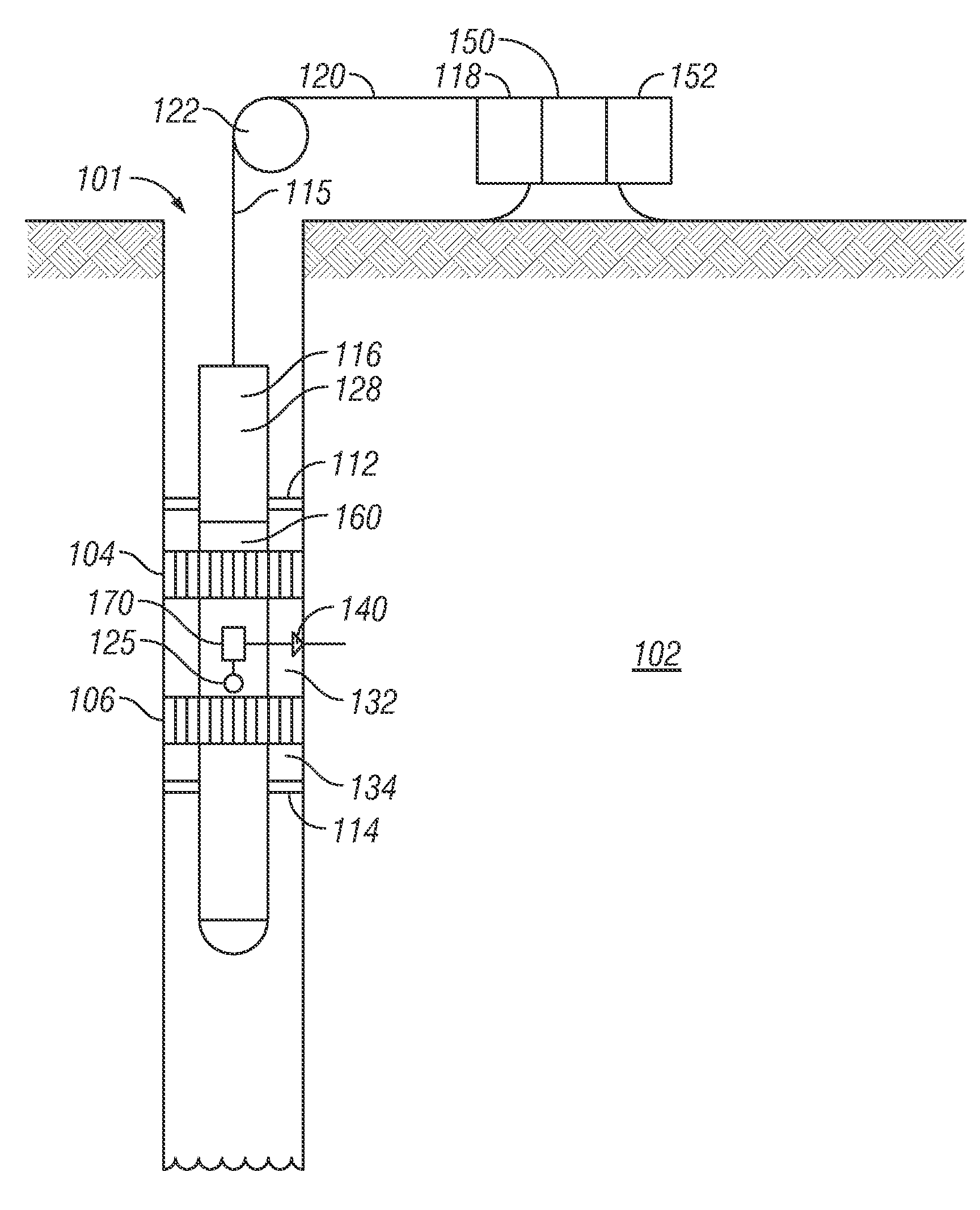
A method of estimating a formation pressure in a wellbore is provided that in one aspect includes measuring a hydrostatic pressure at a selected location in the wellbore, and estimating supercharge pressure as a function of time using a forward model that utilizes the hydrostatic pressure and at least one property of mud in the wellbore that is a function of time. In another aspect, the method may estimate an initial formation pressure at a selected location in a wellbore by obtaining a hydrostatic pressure and at least three formation pressure measurements at three separate times at the selected location, and estimating the initial formation pressure using the hydrostatic pressure, the three pressure measurements and an internal mudcake parameter.

Description

CROSS-REFERENCE TO RELATED APPLICATIONS[0001]This application claims priority from U.S. Provisional Application Ser. No. 60 / 793,484, filed Apr. 20, 2006.BACKGROUND OF THE DISCLOSURE[0002]1. Field of the Invention[0003]This disclosure relates generally to estimating downhole formation pressures.[0004]2. Description of the Related Art[0005]Formation testers are used to measure formation pressures at discrete depths to determine pressure gradients for zones of interest. The pressure gradients are used to identify fluid types and to determine hydraulic connectivity between wells. Pressure gradient quality depends upon the accuracy of the formation pressure measurement. Pressure measurement values are also used to estimate the level of pressure depletion, to check connectivity between different zones, and to control the equivalent circulation density (ECD) during drilling of the wells. Therefore, making accurate pressure measurement at each depth is highly desirable.[0006]Wells are commo...

Claims


Application Information

Patent Timeline
IPC IPC(8): E21B21/08
CPCE21B49/087E21B47/06
Inventor WU, JIANGHUILEE, JAEDONGMEISTER, MATTHIAS
Owner BAKER HUGHES INC
Learn More